
Precooler sealing head, precooler and environment control system

A precooler and head technology, applied in the field of aircraft and aircraft maintenance and manufacturing, can solve the problems of large measurement deviation, reduced equipment service life and high cost, and achieve the effects of easy implementation, reduced possibility of failure and low cost.

Active Publication Date: 2019-11-26
COMAC +1
View PDF7 Cites 0 Cited by
  • Summary
  • Abstract
  • Description
  • Claims
  • Application Information

AI Technical Summary

Problems solved by technology

[0005]1. The temperature sensor arranged downstream of the precooler is far away from the outlet of the precooler, and the average temperature is measured after the gas is evenly mixed. This solution is more accurate for temperature measurement , but the requirements for the layout of the downstream pipeline are relatively high, so the cost of manufacturing is relatively high;
[0006]2. Arrange multiple temperature sensors at the outlet of the precooler, and take the average value of the measurements as the outlet temperature value. This solution requires a higher space for the outlet of the precooler , it is necessary to ensure that there is enough space to arrange multiple sensors, and setting multiple sensors will increase the weight;
[0007]3. Through the ground bench test combined with the CFD flow field simulation, select the point that is close to the average temperature of the outlet as the measurement point of the outlet temperature value. Rack test, the investment time is long, and the selected points cannot meet the average temperature value under different bleed air flow rates at the same time, so the measurement deviation may be large under different circumstances
[0008]In addition, the aircraft will face various severe weather conditions during use, and it is often found that dust and other pollutants are accumulated inside the environmental control equipment during aircraft maintenance. This problem will lead to accelerated wear of the valve movement mechanism of the aircraft and reduce the service life of the equipment

Method used


Image

  • Precooler sealing head, precooler and environment control system
  • Precooler sealing head, precooler and environment control system
  • Precooler sealing head, precooler and environment control system

Examples


Embodiment Construction

[0041] Referring now to the accompanying drawings, specific embodiments of the present invention will be described in detail. What is described here is only a preferred embodiment of the present invention, and those skilled in the art can think of other ways to realize the present invention on the basis of the preferred embodiments, and the other ways also fall within the scope of the present invention.

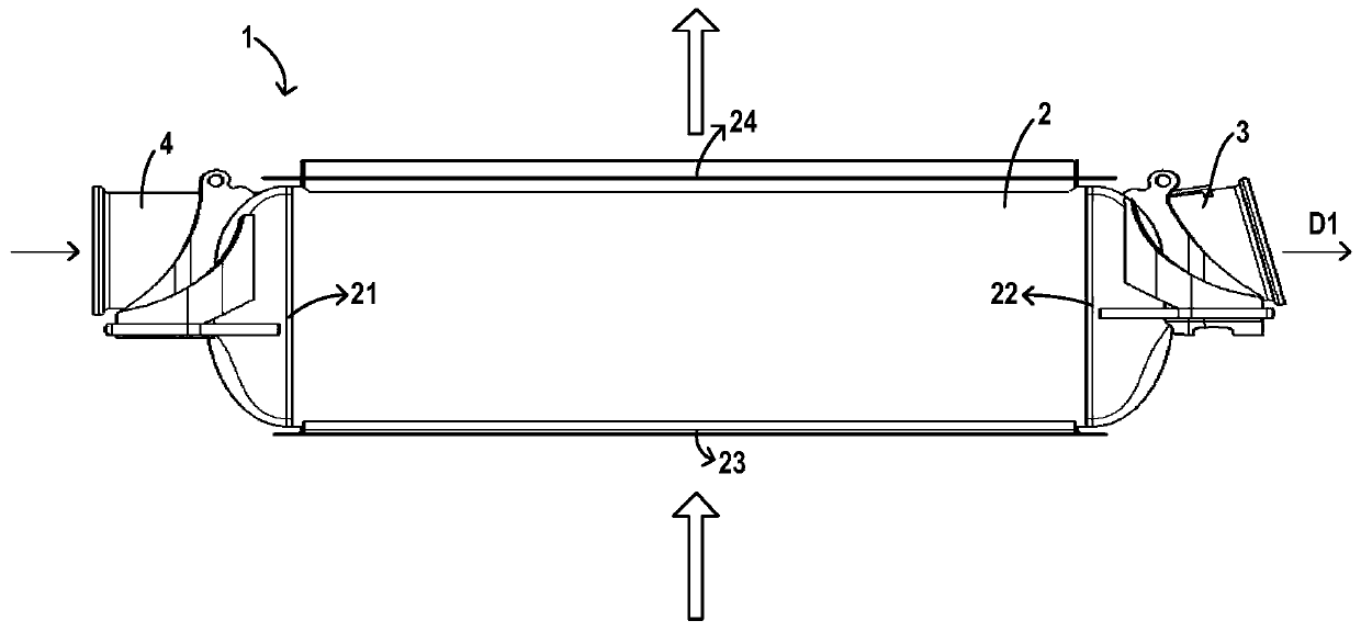
[0042] In a preferred embodiment of the present invention, a precooler head used in an aircraft, a precooler 1 including the precooler head, and an environment control system including the precooler 1 are provided.

[0043] Specifically, the pre-cooler 1 is used to cool down the high-temperature gas drawn from upstream equipment (such as an engine). Such as figure 1 As shown, the precooler 1 includes a precooler main body 2, and the precooler main body 2 is provided with a hot side inlet 21, a hot side outlet 22, a cold side inlet 23 and a cold side outlet 24, and the hot si...


PUM


Abstract

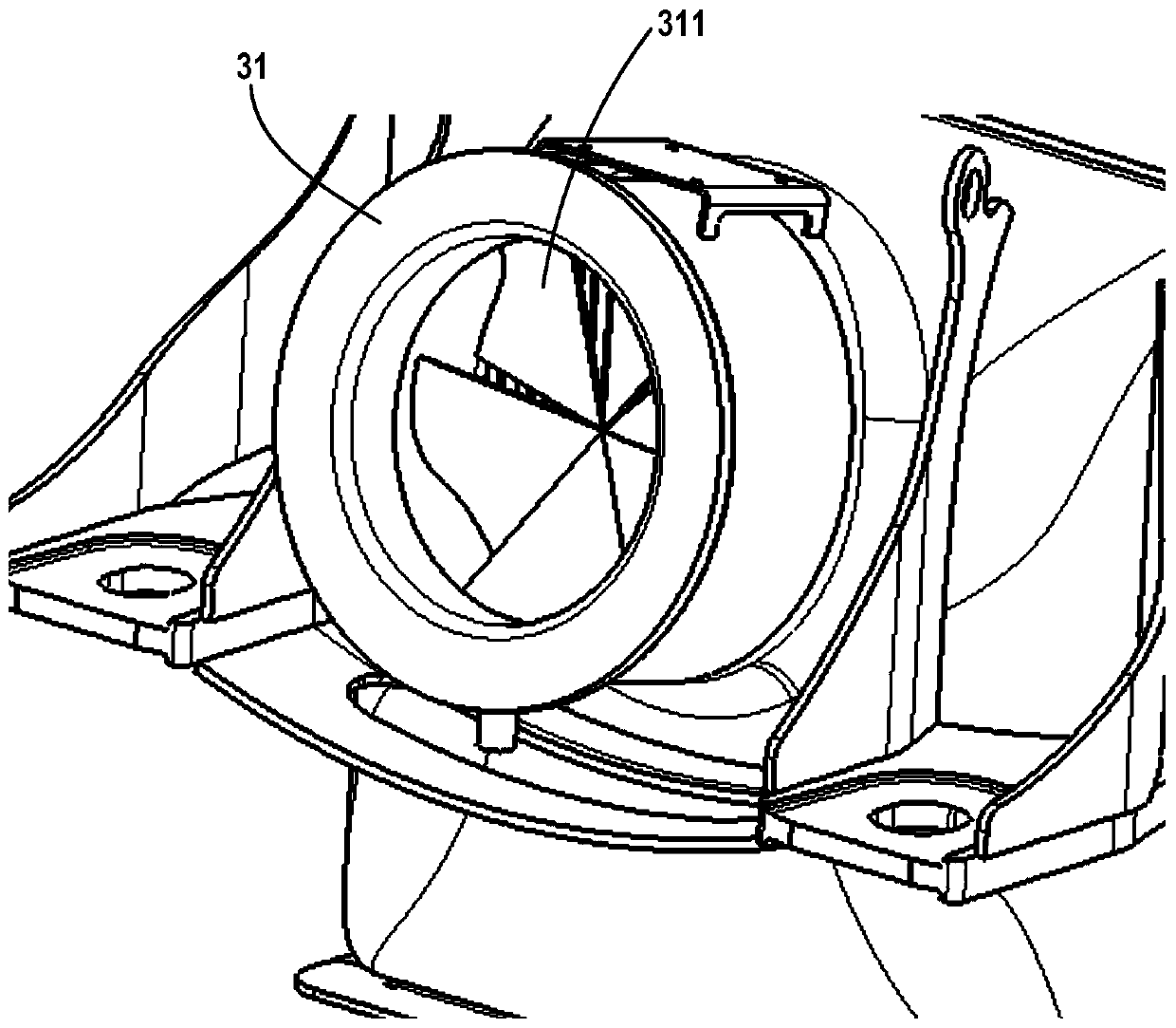
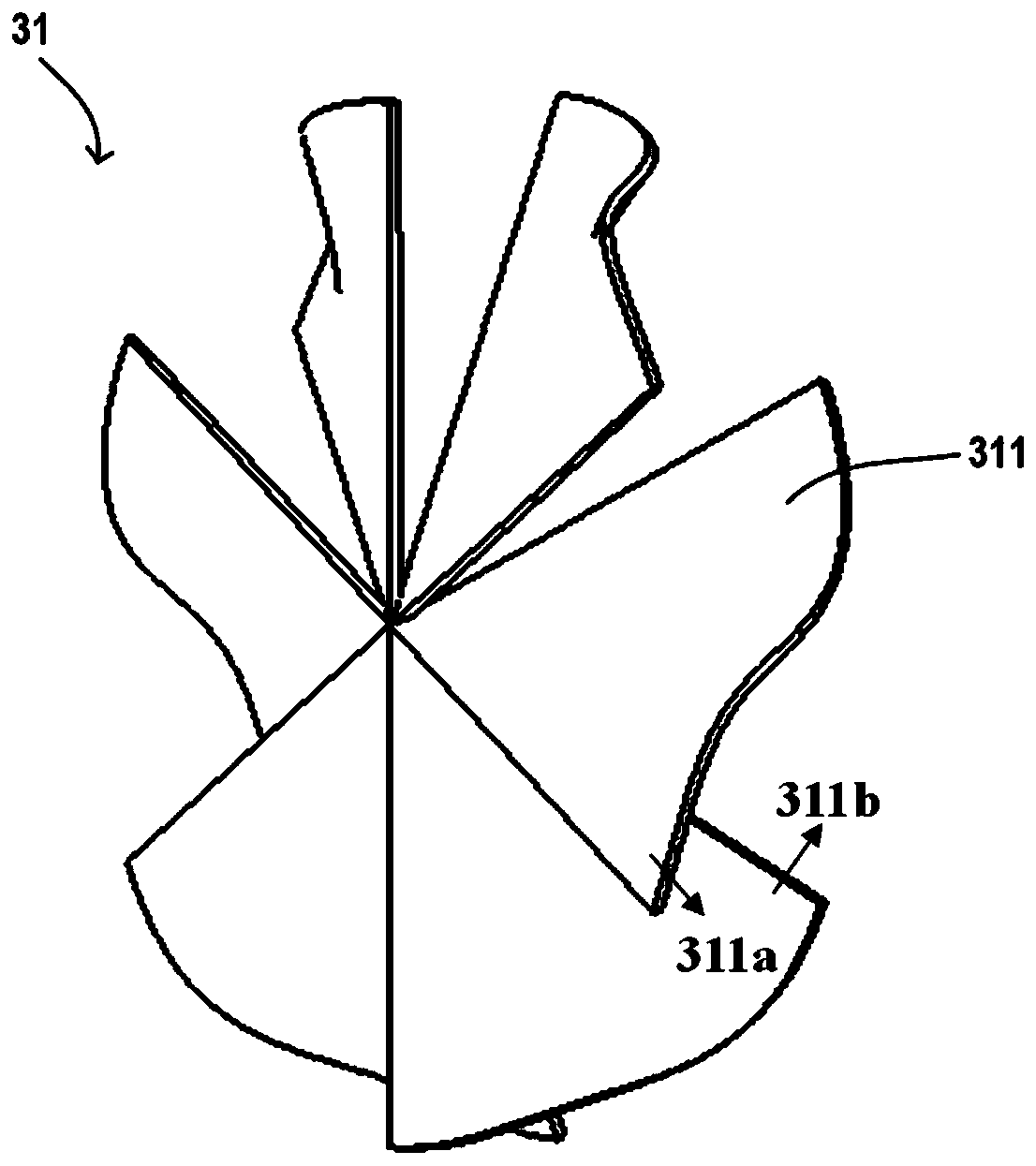
The invention provides a precooler sealing head, a precooler with the precooler sealing head and an environment control system with the precooler. The precooler sealing head is installed at an outletof the precooler for cooling high-temperature air introduced from upstream equipment and comprises a housing and a fan disposed in the housing; the housing is provided with an inlet end and an outletend, wherein the inlet end is configured to be connected with a main body of the precooler, and the outlet end is configured to be connected with a downstream pipeline of the precooler; and the fan comprises multiple centrifugal blades which are fixedly arranged and can form a rotary air flow when air flows through the fan. For the precooler sealing head, the precooler and the environment controlsystem provided by the invention, hot air flows can be rapidly and uniformly mixed when being discharged from the precooler, and a temperature of the air flow is accurately sensed by a temperature sensor at the downstream of the precooler on the premise that no extra space is occupied and a weight at the outlet of the precooler is not increased.

Description

technical field [0001] The invention relates to the field of aircraft and aircraft maintenance and manufacture, in particular to a precooler head, a precooler including the precooler head and an environment control system including the precooler. Background technique [0002] In the composition system of the aircraft, the aircraft environmental control system, as one of the important airborne systems, undertakes the task of providing a comfortable air environment for the crew on board. Crew and passengers provide enough comfortable living and working environment. The main air source of the environmental control system comes from the bleed air of the aircraft engine. The high-temperature compressed air drawn from the engine needs to be cooled by a pre-cooler and adjusted to a suitable temperature value before it can be supplied to the downstream equipment to ensure that the downstream air-conditioning system, machine air demand for wing and engine anti-icing systems, etc. T...

Claims


Application Information

Patent Timeline
Patent Type & Authority Applications(China)
IPC IPC(8): B64D13/06F28F11/02F25B39/00
CPCB64D13/06F28F11/02F25B39/00B64D2013/0603Y02T50/50
Inventor 杜楠楠陈彬司文飞王唯黄晓聃王磊
Owner COMAC
Learn More