Work state detection method for punching production line equipment

A production line equipment and working state technology, which is applied in mechanical equipment, metal processing equipment, fluid pressure actuation system testing, etc., can solve problems such as not very economical and undesirable, single fault signal, and unable to predict the fault trend of the production line, etc., to achieve Reduce equipment maintenance costs, prolong service life, and reduce unnecessary inspection work

Inactive Publication Date: 2019-11-26
戴腾清
View PDF11 Cites 3 Cited by
  • Summary
  • Abstract
  • Description
  • Claims
  • Application Information

AI Technical Summary

Problems solved by technology

[0004] At present, intelligent control has been introduced into modern mechanical equipment, and the failure signal of the mechanical equipment is mostly captured to determine that the mechanical equipment has failed. However, on the one hand, the detection is based on the existence of a clear fault, and it is impossible to predict the failure trend of the production line. On the other hand, the fault signals introduced at present are often relatively single. They may be individual special case data in the normal production process, or data mutations caused by temporary changes in the environment. The above special case data or data mutations do not mean that the equipment is faulty. It is obviously not very economical and not advisable to carry out equipment maintenance for the special data brought by various emergencies in production, especially for stamping production lines with complex and numerous equipment

Method used


Image

  • Work state detection method for punching production line equipment

Examples


Embodiment 1

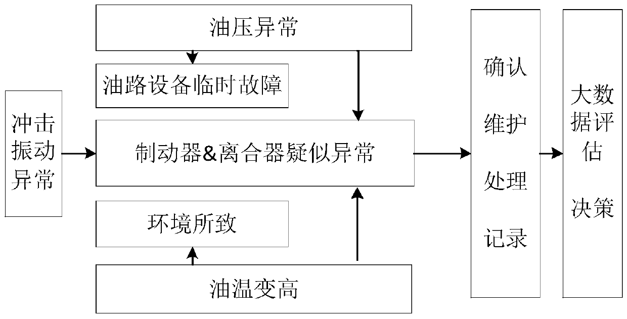
[0028] The core equipment of the stamping production line is the press equipment. The inside of the press equipment mainly controls the press equipment through brakes and clutches. Therefore, when constructing the detection method, focus on parameter detection and evaluation of brakes and clutches. A method for detecting the working status of equipment in a stamping production line, which includes the following steps: Step 1. Collect the oil pressure parameters F(I, T), oil temperature parameters F(X, T) and Shock and vibration parameters F(Y, T), the above parameters have different values ​​based on time or position. Among them, T variable is unified as time variable, T=1, 2, 3,..., t, t+1, and the unit is machine Detection cycle, for example, data is collected once a week. Different values ​​of T represent various parameters of brake & clutch at different times; I, X, and Y variables are position variables, and the values ​​of I, X, Y are: 1, 2, 3...., m (assuming that the st...

Embodiment 2

[0037] The basic implementation steps of this embodiment are the same as those of the first embodiment. The oil pressure trend identification criterion involved can also be a single-point oil pressure time trend identification criterion, and the oil temperature change identification criterion can be a single-point oil temperature change with time. High recognition criterion, vibration trend recognition criterion can be a single point vibration time trend recognition criterion.

[0038] The difference is that the single-point oil pressure time trend identification criterion can be: obtain the oil pressure abnormal point, the oil pressure abnormal point is the oil pressure parameter collected at a single point and is higher than the oil pressure parameters of the two adjacent time points. The threshold h or both of the oil pressure parameters at two adjacent time points are lower than the threshold h, and the frequency of occurrence of abnormal oil pressure points is counted. When t...

Embodiment 3

[0044] The oil pressure trend recognition criterion involved in this embodiment is also the single-point oil pressure time trend recognition criterion, the oil temperature increase recognition criterion is the single-point oil temperature increase recognition criterion with time, and the vibration trend recognition criterion is single Point vibration time trend identification criterion.

[0045] The second embodiment studies the abnormality of the frequency of sudden convex points and sudden concave points in the data, and this embodiment studies the number of abnormal increase or decrease changes in the data as a whole. The single-point oil pressure time trend identification criterion can be: Obtain the oil pressure abnormal point, the oil pressure abnormal point is a sudden change in the average oil pressure parameter collected at a single point, if the number of oil pressure abnormal points reaches n, the criterion is established. In the specific operation, the oil pressure pa...


PUM


Abstract

The invention discloses a work state detection method for punching production line equipment. The work state detection method includes the following steps that firstly, the oil pressure parameters F (I and T), the oil temperature parameters F (X and Y) and the impact vibration parameters F (Y and T) of brakes and clutches of all units on a punching production line are collected regularly corresponding; and secondly, whether the relevant parameters collected in the first step meet the criteria or not is judged according to the oil pressure trend recognition criterion, the oil temperature increasing recognition criterion and the vibration trend recognition criterion, and when all the relevant parameters meet the criteria, suspected abnormal signals of the brakes and the clutches are output for reminding workers to check punching equipment. By means of the method, the combination of various parameter abnormal conditions is used for determining the fault trend of the brakes and clutches, the method differs from a traditional judgment method for determining the work state of the equipment through a single parameter, the misjudgment brought by individual abnormal data normally existing in the production process to the equipment can be avoided, the work state trend of the punching equipment can be foresaw through the judgment on the equipment fault trend, and equipment management is optimized.

Description

Technical field [0001] The invention belongs to the technical field of equipment detection and maintenance, and particularly relates to a method for detecting the working state of a stamping production line equipment. Background technique [0002] As an important application carrier of stamping equipment, stamping automation production line plays an extremely important role in my country's automobile industry system. However, with the improvement of production efficiency, stamping automation production line is increasingly facing the risk of downtime and line stoppage. How to efficiently control equipment In a healthy state, reducing downtime is imminent. Mastering the health status of equipment usually includes two types: predictive maintenance and preventive maintenance. Preventive maintenance is to organize maintenance plans according to a fixed cycle. At present, most of the maintenance plans for stamping production lines are preventive maintenance, but the maintenance plan me...

Claims


Application Information

Patent Timeline
Patent Type & Authority Applications(China)
IPC IPC(8): F16D66/00F15B19/00B21C51/00
CPCB21C51/00F15B19/005F15B2211/87F16D66/00F16D2066/001F16D2066/005F16D2066/008
Inventor 戴腾清
Owner 戴腾清
Why Eureka
Try Eureka