Efficient energy-saving gas-phase drying equipment and operation method thereof
A drying equipment, high-efficiency and energy-saving technology, applied in the direction of drying solid materials, lighting and heating equipment, drying solid materials without heating, etc., can solve the problems of difficult recovery of kerosene, inability to transport quickly, high temperature of kerosene, etc., to reduce temperature, Improve heat exchange efficiency and increase the effect of heat exchange area
- Summary
- Abstract
- Description
- Claims
- Application Information
AI Technical Summary
Problems solved by technology
Method used
Image

Examples
Embodiment 1
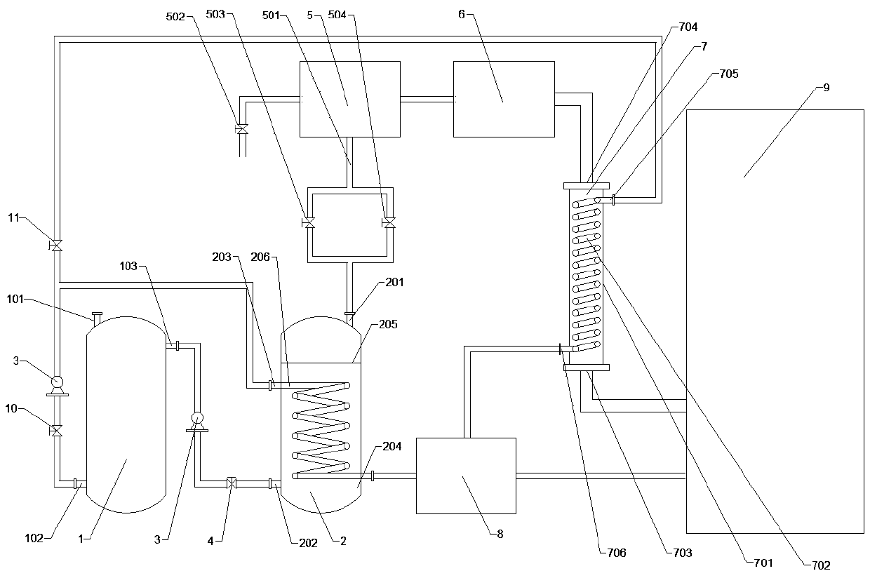
[0029] Such as figure 1 A high-efficiency and energy-saving gas-phase drying equipment shown is composed of a kerosene storage tank, an oil-water separator 5, a condenser 6, a heat exchanger 7, an evaporator 8 and a vacuum drying tank 9;
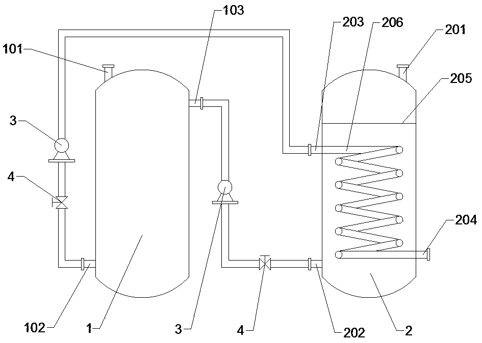
[0030] The kerosene storage tank as described image 3 As shown, it consists of crude oil tank 1 and buffer tank 2;
[0031] The crude oil tank 1 is provided with a crude oil inlet a 101, a crude oil outlet a 102 and a recovered oil inlet a 103; the crude oil inlet a 101 is arranged on the top of the crude oil tank 1, and the crude oil outlet a 102 is arranged in the crude oil tank 1 on the bottom side, the recovered oil inlet a103 is set on the upper side of the crude oil tank 1;
[0032] The buffer tank 2 is provided with a recovery oil inlet b 201, a recovery oil outlet 202, a crude oil inlet b 203 and a crude oil outlet b204; the buffer tank 2 is provided with a filter screen 205 and a heat exchange pipeline 206, and the filter screen ...
Embodiment 2
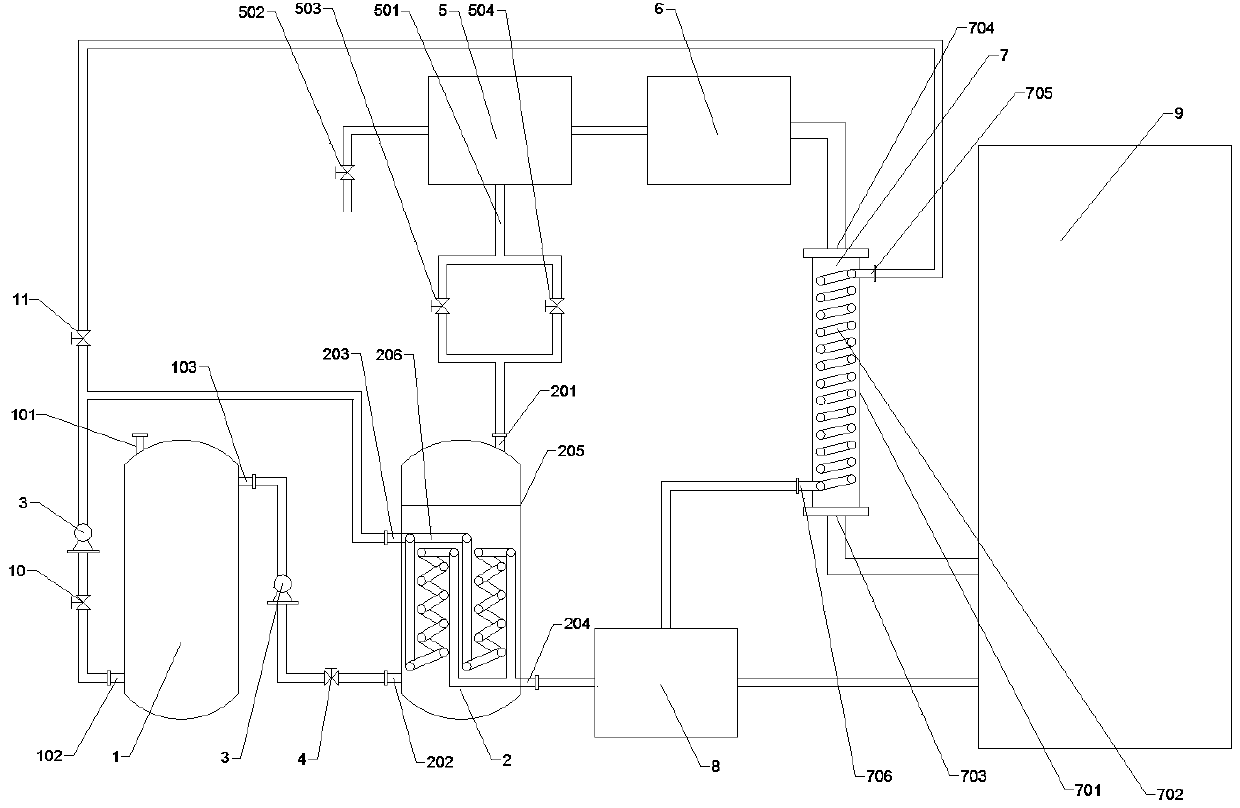
[0043] like figure 2 A high-efficiency and energy-saving gas-phase drying equipment shown is composed of a kerosene storage tank, an oil-water separator 5, a condenser 6, a heat exchanger 7, an evaporator 8 and a vacuum drying tank 9;
[0044] The kerosene storage tank as described Figure 4 As shown, it consists of crude oil tank 1 and buffer tank 2;
[0045] The crude oil tank 1 is provided with a crude oil inlet a 101, a crude oil outlet a 102 and a recovered oil inlet a 103; the crude oil inlet a 101 is arranged on the top of the crude oil tank 1, and the crude oil outlet a 102 is arranged in the crude oil tank 1 on the bottom side, the recovered oil inlet a103 is set on the upper side of the crude oil tank 1;
[0046] The buffer tank 2 is provided with a recovery oil inlet b 201, a recovery oil outlet 202, a crude oil inlet b 203 and a crude oil outlet b204; the buffer tank 2 is provided with a filter screen 205 and a heat exchange pipeline 206, and the filter screen 2...
PUM
 Abstract
Description
Claims
Application Information
 - R&D
- Intellectual Property
- Life Sciences
- Materials
- Tech Scout
- Unparalleled Data Quality
- Higher Quality Content
- 60% Fewer Hallucinations
Browse by: Latest US Patents, China's latest patents, Technical Efficacy Thesaurus, Application Domain, Technology Topic, Popular Technical Reports.
© 2025 PatSnap. All rights reserved.Legal|Privacy policy|Modern Slavery Act Transparency Statement|Sitemap|About US| Contact US: help@patsnap.com