Differential charge pump circuit with operational amplifier

An operational amplifier, charge pump technology, applied in the direction of electrical components, automatic power control, etc., can solve the problems of increasing charge and discharge current, changing the bandwidth of the PLL loop of the phase-locked loop, etc., to improve the mismatch between charge current and discharge current. Effect

Active Publication Date: 2019-11-26
TIANJIN JINHANG COMP TECH RES INST
View PDF6 Cites 1 Cited by
  • Summary
  • Abstract
  • Description
  • Claims
  • Application Information

AI Technical Summary

Problems solved by technology

As the output voltage increases, the charge and discharge current increases due to the effect of channel length modulation, thus changing the bandwidth of the PLL loop

Method used


Image

  • Differential charge pump circuit with operational amplifier
  • Differential charge pump circuit with operational amplifier

Examples


Embodiment Construction

[0052] In order to make the purpose, content, and advantages of the present invention clearer, the specific embodiments of the present invention will be further described in detail below with reference to the accompanying drawings and embodiments.

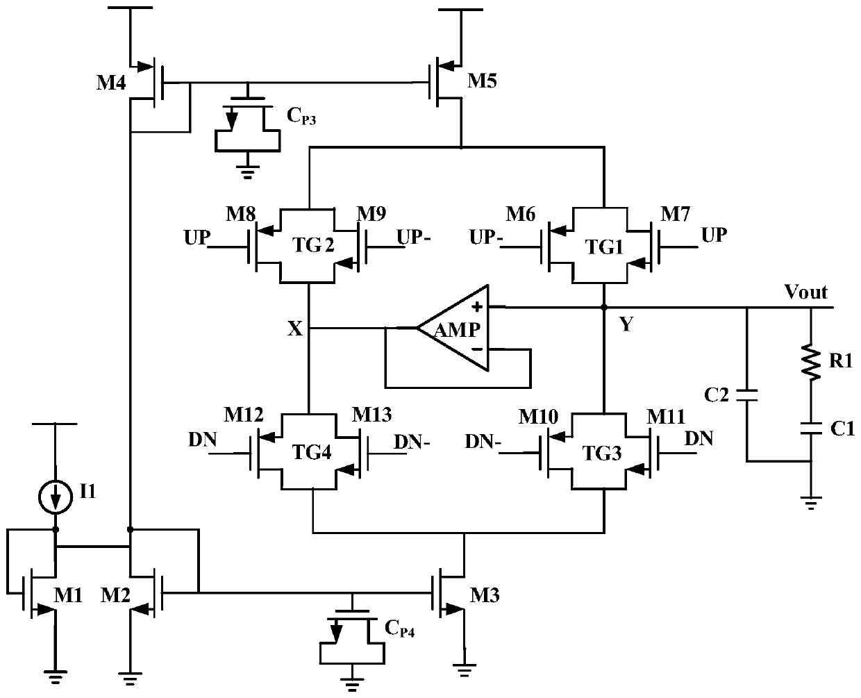
[0053] In order to solve the problems of the prior art, the present invention provides a differential charge pump circuit with an operational amplifier, such as figure 2 As shown, the differential charge pump circuit includes: a current source I1, a pull-up current mirror, a pull-down current mirror, a transmission gate switch, an operational amplifier, a first resistor R1, a first capacitor C1, a second capacitor C2, and a third capacitor Cp3 and the fourth capacitor CP4; the third capacitor Cp3 and the fourth capacitor CP4 are grounded;

[0054] The pull-up current mirror is used to convert the reference source current into the charging current of the charge pump;

[0055] the pull-down current mirror is used to convert the ref...


PUM


Abstract

The invention belongs to the technical field of integrated circuit design, and relates to a differential charge pump circuit with an operational amplifier. The differential charge pump circuit comprises a current source I1, a pull-up current mirror, a pull-down current mirror, a transmission gate switch, the operational amplifier, a first resistor R1, a first capacitor C1, a second capacitor C2, athird capacitor Cp3 and a fourth capacitor CP4. The differential charge pump circuit has the following beneficial effects that (1) the problem that the charging current and the discharging current ofa traditional charge pump are not matched is solved; ; (2) the problem of clock feed-through is solved; and (3) the charge sharing effect influence is improved.

Description

technical field [0001] The invention belongs to the technical field of integrated circuit design, and in particular relates to a differential charge pump circuit with an operational amplifier, which is mainly applied to a phase-locked loop circuit in a high-speed application environment. Background technique [0002] The charge pump is an important unit circuit that composes the phase-locked loop. It is connected to the frequency discriminator PFD and the voltage-controlled oscillator VCO, and plays a key role in the performance of the entire phase-locked loop. In the high-speed application environment, the requirements for the charge pump are particularly high, and the glitch and jitter of the output voltage of the charge pump need to be considered. [0003] However, in the actual design, the charge pump has problems such as leakage current, current mismatch, timing mismatch, and the change of charge and discharge current with the output voltage. Among them, the current mi...

Claims


Application Information

Patent Timeline
Patent Type & Authority Applications(China)
IPC IPC(8): H03L7/089
CPCH03L7/0891Y02B70/10
Inventor 晋超超朱天成候俊马
Owner TIANJIN JINHANG COMP TECH RES INST
Why Eureka
Try Eureka