
Industrial waste gas treatment device with monitoring function

A technology for industrial waste gas and treatment devices, which is applied in gas treatment, mixers with rotating stirring devices, combined devices, etc., can solve the problems of lack of waste gas treatment effect adjustment function, lack of gas composition monitoring function, and reduce system volume, etc., to achieve Improve the effect of waste gas treatment, increase the area and probability, and ensure the effect of treatment effect

Pending Publication Date: 2019-12-03
苏州仕净科技股份有限公司
View PDF9 Cites 8 Cited by
  • Summary
  • Abstract
  • Description
  • Claims
  • Application Information

AI Technical Summary

Problems solved by technology

The waste gas treatment system has the advantages of efficient treatment of waste gas, but the system structure is complex and the energy consumption is high
[0005] Another example is the patent: CN208372775U, which discloses a waste gas treatment system, which includes a first shell for holding the adsorption liquid. After entering the first waste gas inlet, the waste gas passes through a plurality of blades and is discharged from the first waste gas outlet. The exhaust gas treatment system also includes a second housing, the second housing is provided with a second exhaust gas inlet for the purified gas to enter, and a second exhaust gas outlet for the purified gas to discharge, which absorbs the adsorption liquid through the blades, and then the gas passes through the The harmful substances in the blades are absorbed by the adsorption liquid, which reduces the volume of the system. When the blades still need a driving device to drive the blades to rotate, the energy consumption is large. In addition, the gas treated by the blades directly enters the next operation, which lacks the effect of waste gas treatment. regulation function, and lacks the monitoring function of the final exhausted gas composition

Method used


Image

  • Industrial waste gas treatment device with monitoring function
  • Industrial waste gas treatment device with monitoring function
  • Industrial waste gas treatment device with monitoring function

Examples


Embodiment Construction

[0049] The present invention will be further described in detail below in conjunction with the embodiments, so that those skilled in the art can implement it with reference to the description.

[0050] It should be understood that terms such as "having", "comprising" and "including" used herein do not exclude the presence or addition of one or more other elements or combinations thereof.

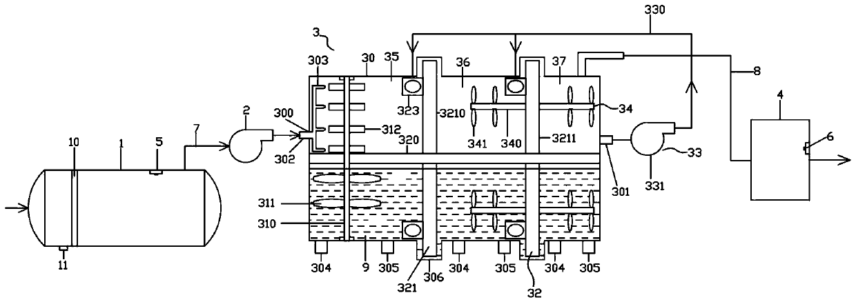
[0051] Such as figure 1 As shown, an industrial waste gas treatment device with a monitoring function in this embodiment includes a buffer tank 1, an air intake fan 2, a waste gas treatment tank 3, a filter device 4, and a first gas set arranged in sequence along the airflow direction. The monitoring device 5 and the second gas monitoring device 6 arranged at the gas outlet end of the filter device 4 .

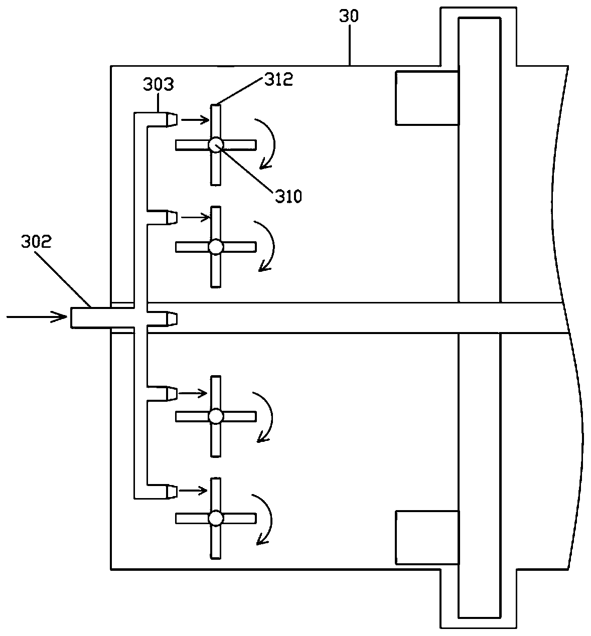
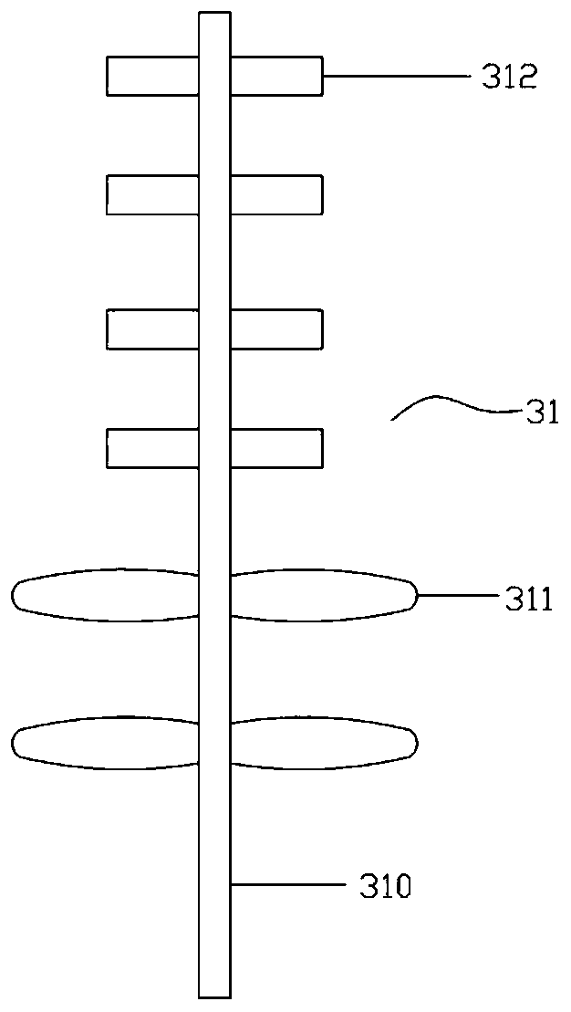
[0052] The exhaust gas treatment tank 3 includes a cylindrical treatment tank body 30, a main stirring device 31 disposed inside the treatment tank body 30 along the vertical direction, and...


PUM


Abstract

The invention discloses an industrial waste gas treatment device with a monitoring function. The industrial waste gas treatment device with the monitoring function comprises a buffering tank, a gas inlet fan, a waste gas treatment tank, a filtering device, a first gas monitoring device and a second gas monitoring device, wherein the buffering tank, the gas inlet fan, the waste gas treatment tank and the filtering device are arranged sequentially along the gas flow direction; the first gas monitoring device is arranged in the buffering tank; the second gas monitoring device is arranged at the gas outlet end of the filtering device; and the waste gas treatment tank comprises a cylindrical treatment tank body, a main stirring device, a gas treatment disk assembly and a gas circulating assembly. According to the industrial waste gas treatment device with the monitoring function, the waste gas is filtered in advance through a filtering net in the buffering tank, and the waste gas is treatedsequentially by the waste gas treatment tank and the filtering device, so that good process waste gas treatment effect can be achieved, and the device is simple in structure.

Description

technical field [0001] The invention relates to the technical field of waste gas treatment, in particular to an industrial waste gas treatment device with a monitoring function. Background technique [0002] With the rapid development of industrialization, it is inevitable to produce a large amount of industrial waste gas, such as acid waste gas, organic waste gas and so on. Acid exhaust gas mainly includes sulfur oxides, nitrogen oxides, H 2 S, chlorine, etc., a large amount of acid waste gas has caused the formation of acid rain. Acid rain has a great impact on the environment. Acid rain has the greatest impact on trees, which can be fatal and seriously affect the living environment of human beings. Therefore, the whole world pays special attention to the environment and formulates many measures. To reduce the production of factories that pollute the air, develop a green economy, and live a green life. Organic waste gas includes formaldehyde, xylene, toluene, acetone, me...

Claims


Application Information

Patent Timeline
Patent Type & Authority Applications(China)
IPC IPC(8): B01D53/75B01D53/78B01D53/68B01D53/56B01D53/52B01D53/50B01D53/40B01D53/04B01D50/00B01D46/30B01D46/00B01F13/10B01F7/18
CPCB01D53/75B01D53/78B01D53/40B01D53/50B01D53/502B01D53/52B01D53/523B01D53/56B01D53/68B01D46/0012B01D46/0036B01D53/04B01D46/30B01D2251/604B01D2251/304B01D2251/60B01D2257/7027B01D46/62B01F27/90B01F33/81B01D50/60
Inventor 董仕宏吴倩倩张世忠
Owner 苏州仕净科技股份有限公司
Learn More