Light-splitting dispersion device for inductively-coupled plasma emission spectrometer

A plasma and inductive coupling technology, applied in the directions of emission spectroscopy, spectrometry/spectrophotometry/monochromator, using diffractive elements to generate spectra, etc., which can solve the channel with limited number of elements and inconvenient addition of elements , poor flexibility and other problems, to achieve the effect of wide wavelength coverage, easy installation and debugging, stable and reliable instrument

Inactive Publication Date: 2019-12-03
山东东仪光电仪器有限公司 +1
View PDF6 Cites 0 Cited by
  • Summary
  • Abstract
  • Description
  • Claims
  • Application Information

AI Technical Summary

Problems solved by technology

[0002] At present, the inductively coupled plasma emission spectrometer adopts spectroscopic systems including Paschen-Runge optical path, Czerny-Turner optical path and echelle optical path. Paschen-Runge optical path usually uses photomultiplier tubes as detectors. The disadvantage is that it is less flexible and inconvenient to add The channel of the element, the number of determined elements is limited
The disadvantage of the Czerny-Turner optical path is that the motor drives the grating to rotate to achieve wavelength scanning analysis, which involves a transmission mechanism, so the stability is poor. In addition, the wavelength coverage is narrow
The disadvantage of the echelle optical path is that the optical path is complex and the spectrum analysis is difficult. The spectroscopic system needs to use an echelle grating and an area array CCD, so the manufacturing cost of the instrument is very high

Method used


Image

  • Light-splitting dispersion device for inductively-coupled plasma emission spectrometer
  • Light-splitting dispersion device for inductively-coupled plasma emission spectrometer

Examples


Embodiment Construction

[0017] The principles and features of the present invention are described below in conjunction with the accompanying drawings, and the examples given are only used to explain the present invention, and are not intended to limit the scope of the present invention.

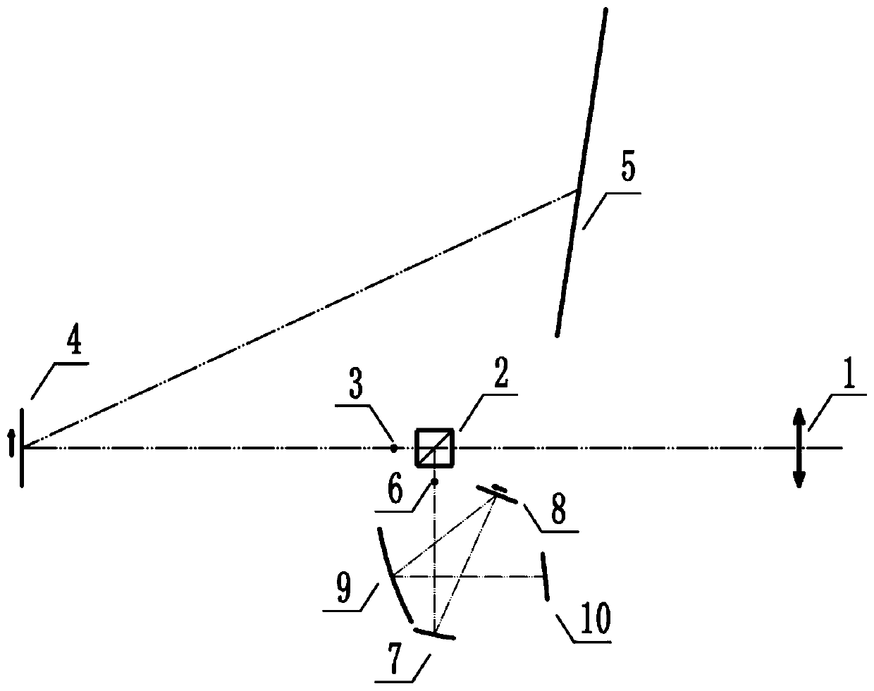
[0018] Such as figure 1 As shown, the optical signal emitted by the inductively coupled plasma light source is focused by the converging lens 1, and then directed to the semi-reflective and semi-transparent prism 2 and divided into two optical paths at the same time, which are the transmitted optical path and the reflected optical path; the transmitted optical path passes through the flat field slit and the optical path After the diaphragm assembly 3 reaches the flat-field grating 4, and then after being dispersed by the flat-field grating, it reaches the linear array CCD detector A 5 to detect the optical signal. There are 7 linear array CCD detectors A 5, and the wavelength coverage range is 170-450nm. The reflect...


PUM


Abstract

The invention discloses a light-splitting dispersion device for an inductively-coupled plasma emission spectrometer. The light-splitting dispersion device comprises a converging lens, a beam splittermirror and gratings in the light path propagation direction. The beam splitter mirror is a semi-reflecting and semi-transmitting prism. The number of the gratings is two, and the gratings are a flat field grating and a plane grating respectively. After optical signals emitted by a light source are focused by the converging lens, the light is divided into two beams through the semi-reflecting and semi-transmitting prism, wherein the two beams are transmission light and reflection light respectively, the transmission light being dispersed and split by the flat field grating, and the reflection light being dispersed and split by the plane grating.

Description

technical field [0001] The invention relates to a spectroscopic dispersion device for an inductively coupled plasma emission spectrometer. Background technique [0002] At present, the inductively coupled plasma emission spectrometer adopts spectroscopic systems including Paschen-Runge optical path, Czerny-Turner optical path and echelle optical path. Paschen-Runge optical path usually uses photomultiplier tubes as detectors. The disadvantage is that it is less flexible and inconvenient to add Element channel, the number of measured elements is limited. The disadvantage of the Czerny-Turner optical path is that the motor drives the grating to rotate to realize the wavelength scanning analysis, which involves a transmission mechanism, so the stability is poor. In addition, the wavelength coverage is narrow. The disadvantage of the echelle optical path is that the optical path is complex and the spectrum analysis is difficult. The spectroscopic system needs to use an echelle ...

Claims


Application Information

Patent Timeline
Patent Type & Authority Applications(China)
IPC IPC(8): G01J3/02G01J3/18G01J3/28G01J3/443G01N21/73
CPCG01J3/0208G01J3/18G01J3/1804G01J3/2803G01J3/2823G01J3/443G01N21/73
Inventor 张勇赵珍阳王世功许玉兴田中朝张春梅张丽玫
Owner 山东东仪光电仪器有限公司
Why Eureka
Try Eureka