
Method for measuring refractive index by using conical coreless optical-fiber-cascaded hollow-core optical fiber structure

A technology of coreless optical fiber and hollow-core optical fiber, which is applied in the field of measuring refractive index by using tapered coreless optical fiber cascaded hollow-core optical fiber structure, which can solve the problems of poor stability, temperature crosstalk, low sensitivity and resolution, etc., and achieve high sensitivity , low temperature sensitivity, and the effect of simplifying the measurement process

Pending Publication Date: 2019-12-03
HENAN NORMAL UNIV
View PDF5 Cites 4 Cited by
  • Summary
  • Abstract
  • Description
  • Claims
  • Application Information

AI Technical Summary

Problems solved by technology

[0003] In order to solve the problems of poor stability, low sensitivity and resolution in the range of low refractive index, and temperature crosstalk of the optical fiber spectral refractive index sensing system based on Mach-Zehnder interferometer, the present invention provides a cascade sensor using tapered coreless optical fiber. A method for measuring the refractive index of a hollow-core fiber structure. This method realizes the measurement of the refractive index by analyzing and studying the influence of different refractive indices on the wavelength and intensity of the transmission spectrum interference peak of the tapered coreless fiber cascaded hollow-core fiber structure.

Method used


Image

  • Method for measuring refractive index by using conical coreless optical-fiber-cascaded hollow-core optical fiber structure
  • Method for measuring refractive index by using conical coreless optical-fiber-cascaded hollow-core optical fiber structure
  • Method for measuring refractive index by using conical coreless optical-fiber-cascaded hollow-core optical fiber structure

Examples


Embodiment Construction

[0016] The above-mentioned contents of the present invention are described in further detail below through the embodiments, but this should not be interpreted as the scope of the above-mentioned themes of the present invention being limited to the following embodiments, and all technologies realized based on the above-mentioned contents of the present invention all belong to the scope of the present invention.

[0017] (1) Tapered coreless fiber cascaded hollow-core fiber structure measurement system for refractive index

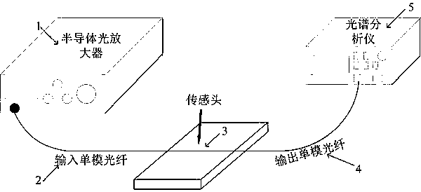
[0018] The optical fiber refractive index measurement system is composed of a semiconductor optical amplifier 1, an input single-mode fiber 2, a tapered coreless fiber cascaded hollow-core fiber 3, an output single-mode fiber 4 and a spectrum analyzer 5.

[0019] (2) Measurement of Refractive Index

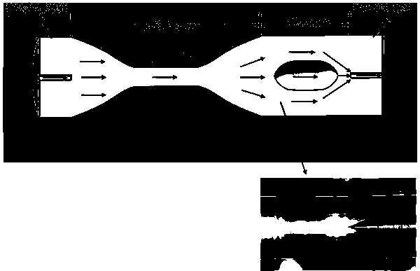
[0020] Broadband light (wavelength range from 1200-1700nm) comes out of the semiconductor optical amplifier through the input single-mode fiber and the tapered ...


PUM

PropertyMeasurementUnit
refractive indexaaaaaaaaaa

Abstract

The invention discloses a method for measuring a refractive index by using a conical coreless optical-fiber-cascaded hollow-core optical fiber structure. The specific refractive index measurement process is implemented as follows: arranging a conical coreless optical-fiber-cascaded hollow-core optical fiber as a sensing head in a room temperature environment and fixing the prepared sensing head ona slide stably and horizontally by using ultraviolet glue to prevent fiber bending; immersing the sensor into NaCl aqueous solutions with different concentrations, namely different refractive indexes, recording a transmission spectrum, purifying the sensing head by using deionized water, recovering an original spectrum in air, then immersing the sensing head into a new NaCl aqueous solution, recording a new transmission spectrum, and finally acquiring a corresponding linear relationship between the changes of the wavelength and intensity of the transmission spectrum and the refractive index and realizing the measurement of the refractive index according to the corresponding linear relationship. According to the invention, the thermal expansion coefficient of the coreless optical fiber islow and thus the sensor has extremely low temperature sensitivity, so that a problem of temperature crosstalk can be effectively solved.

Description

technical field [0001] The invention belongs to the technical field of optical fiber spectrum sensing, and in particular relates to a method for measuring the refractive index by using a tapered coreless optical fiber cascaded hollow-core optical fiber structure. Background technique [0002] In recent years, refractive index measurement has played an important role in chemical and biological fields such as chemical experiments, food quality and safety monitoring, environmental monitoring, and biological reactions. Optical fiber refractive index sensors are characterized by their compact structure, high detection accuracy, good aging resistance, and energy The unique advantages of working in a chemically hazardous environment and the inherent ability to resist external electromagnetic interference have been extensively studied. Among various optical fiber refractive index sensors, sensors based on Mach-Zehnder interferometers have attracted widespread attention due to their ...

Claims


Application Information

Patent Timeline
Patent Type & Authority Applications(China)
IPC IPC(8): G01N21/45
CPCG01N21/45G01N2021/458
Inventor 常钦王芳马涛庞凯博王旭刘玉芳
Owner HENAN NORMAL UNIV
Learn More