Distortion radar signal modelling method under time-varying plasma sheath

A plasma sheath and radar signal technology, which is applied in the field of modeling of distorted radar signals under the ion sheath, can solve the problems that the description of the radar signal cannot be distorted, and it is difficult to reflect the influence of the time-varying plasma sheath on the modulation of the radar signal.

Active Publication Date: 2019-12-03
XIDIAN UNIV
View PDF11 Cites 7 Cited by
  • Summary
  • Abstract
  • Description
  • Claims
  • Application Information

AI Technical Summary

Problems solved by technology

This time-varying characteristic will produce a more complex amplitude-phase modulation effect on the signal. In addition, considering the particularity and complexity of the radar signal, the signal is multi-frequency, or even frequency-modulated or frequency-hopping. The steady-state plasma sheath pair It is difficult to reflect the influence of the time-varying plasma sheath on the modulation of radar signals in the relevant research on the influence of single-frequency signals;
[0005] The existing traditional radar signal modeling methods are very mature, but the modulation effect on the amplitude and phase of the distorted radar signal under the time-varying plasma sheath cannot be analyzed only by traditional modeling methods
If only the traditional radar signal model cannot reflect the parasitic modulation of the plasma sheath, it cannot describe the distorted radar signal under the plasma sheath more accurately
[0006] Therefore, when analyzing the distorted radar signal under the time-varying plasma sheath, the above method is no longer tried. Objectively, a realistic time-varying plasma sheath distortion radar signal modeling is required to modulate the time-varying plasma sheath. to analyze

Method used


Image

  • Distortion radar signal modelling method under time-varying plasma sheath
  • Distortion radar signal modelling method under time-varying plasma sheath
  • Distortion radar signal modelling method under time-varying plasma sheath

Examples


Embodiment 1

[0026] At present, relevant research on radar signals without plasma sheaths and single-frequency signals under steady-state plasma sheaths already exists. The modulation effect of the radar is complicated, and the existing relevant research cannot accurately analyze the influence of the time-varying plasma sheath on the distorted radar signal. The present invention researches and discusses the modeling method of the distorted radar signal under the time-varying plasma sheath. The invention aims at theoretically modeling the distorted radar signal under the time-varying plasma sheath, and determines the modulation influence on the amplitude and phase of the distorted radar signal from the real part and the imaginary part of the transmission coefficient of the time-varying plasma sheath.

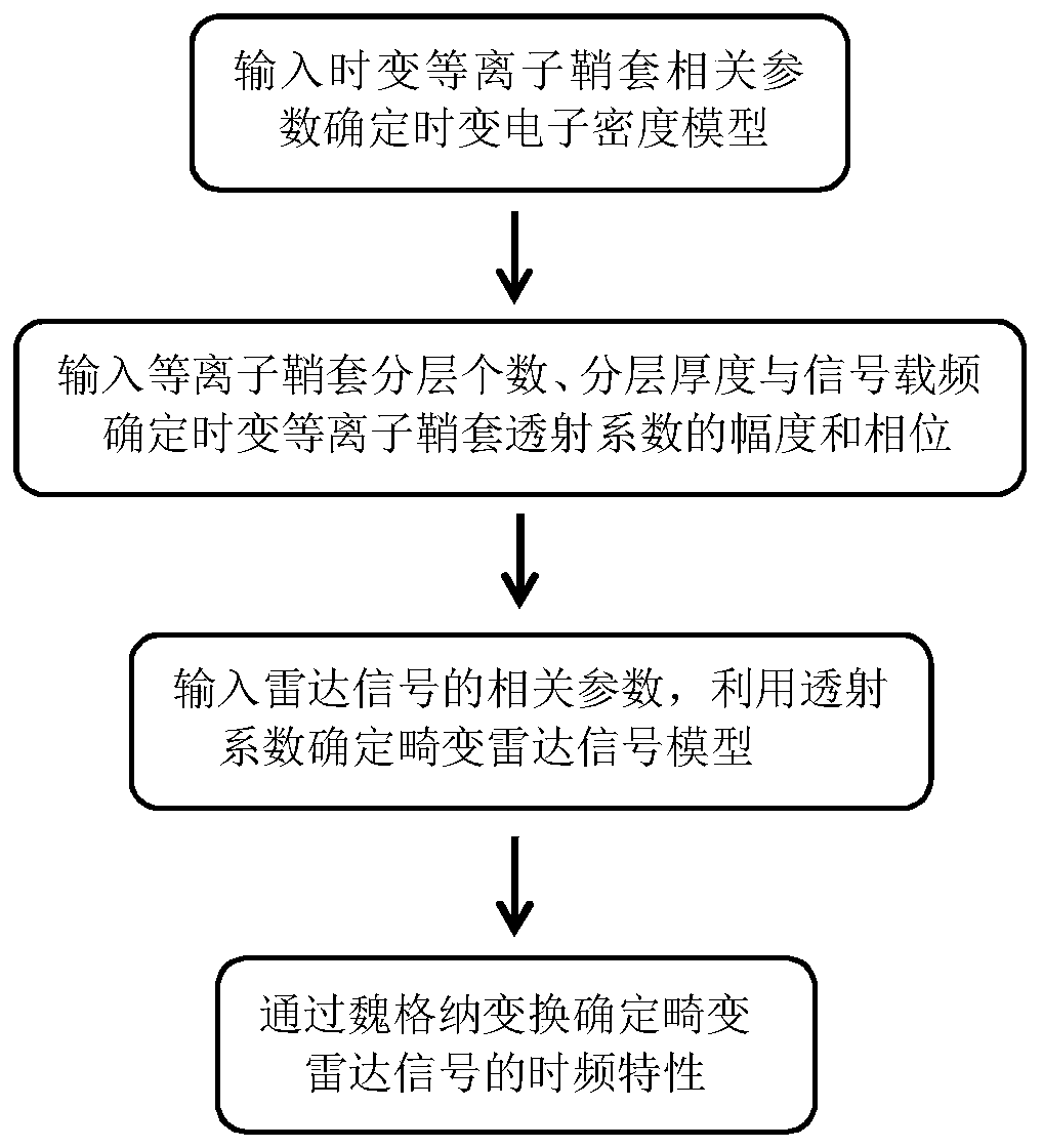
[0027] The present invention is a radar signal modeling method under a time-varying plasma sheath, see figure 1 , the radar signal modeling method under the time-varying plasma sheath include...

Embodiment 2

[0042] The modeling method of the distorted radar signal under the time-varying plasma sheath is the same as in Embodiment 1, and the calculation in step S2 obtains the time-varying plasma sheath transmission coefficient T dyn (t,f 0 ), including the following steps:

[0043] 2.1) Calculate the time-varying plasma characteristic frequency ω of the mth layer p (t,z m ): input electron mass m e , the time-varying plasma sheath electron density model Ne calculated by step S1 dyn (z,t), determine the time-varying plasma characteristic frequency ω of the mth layer p (t,z m ), the time-varying plasma characteristic frequency of the mth layer, specifically expressed as follows:

[0044]

[0045] 2.2) Calculate the time-varying plasma sheath complex permittivity ε(t,z m , f 0 ): Input the time-varying electron collision frequency v of the plasma sheath en , using the time-varying plasma sheath electron density model Ne dyn (z,t), from the time-varying plasma sheath charac...

Embodiment 3

[0056] The modeling method of the distorted radar signal under the time-varying plasma sheath is the same as in Embodiment 1-2, and the calculation of the distorted signal model formed by the radar signal passing through the time-varying plasma sheath described in step S3 includes the following steps:

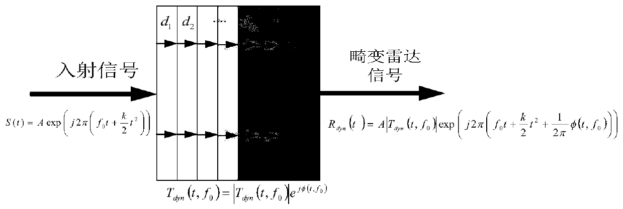
[0057] 3.1) Input chirp radar signal S(t): input radar signal carrier frequency f 0 , radar signal amplitude A, radar signal modulation frequency k and radar signal pulse width T P , to determine the chirp signal radar model S(t):

[0058]

[0059] 3.2) Determine the distortion radar signal model R dyn (t): the amplitude of the transmission coefficient of the time-varying plasma sheath|T dyn (t,f 0 )| and phase φ(t,f 0 ) and the chirp signal radar model S(t), jointly determine the distorted radar signal R dyn (t), that is, the distortion radar signal model R dyn (t).

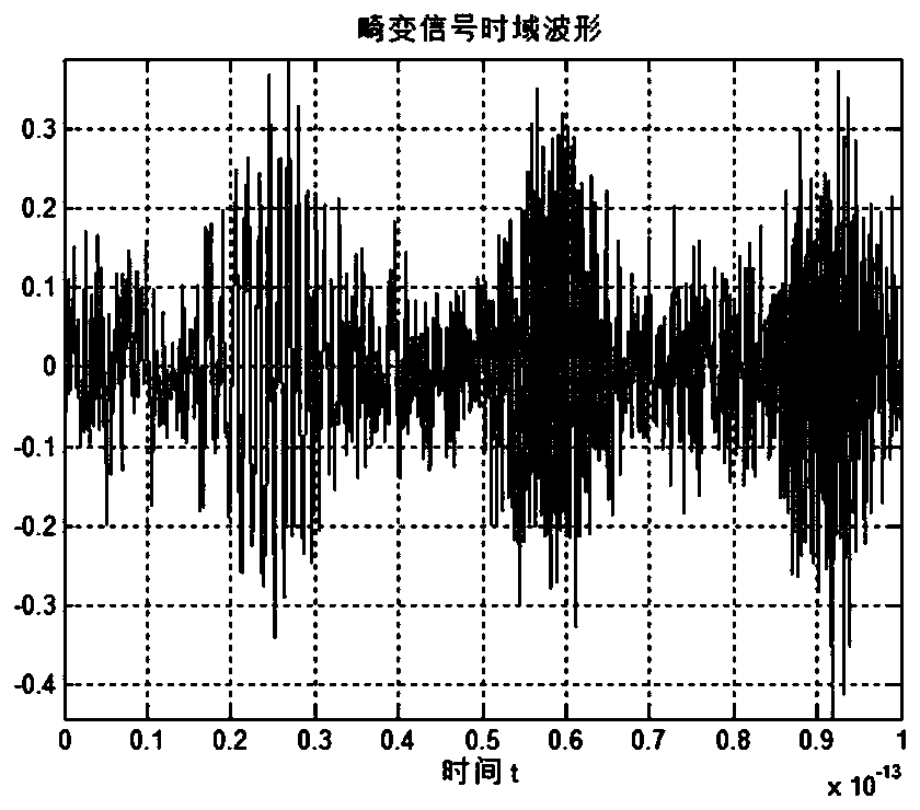
[0060] Based on the determination of the distorted radar signal, the present invention can find the ...


PUM


Abstract

The invention discloses a distortion radar signal modelling method under a time-varying plasma sheath. The problem that the traditional radar signal model is hard to perform simulation and analysis ona modulation effect received by a distortion radar signal is realized. The realization process is as follows: establishing an electronic density model of the time-varying plasma sheath; computing a plasma sheath transmission coefficient and amplitude and phase thereof; computing to obtain the distortion radar signal model; and performing time-frequency processing on the distortion radar signal model. Through the modelling and time-frequency processing on the distortion radar signal under the time-varying plasma sheath, the distortion radar signal amplitude and phase modulation condition and time-frequency curve intercept and slope change thereof are determined. Through the method disclosed by the invention, the disadvantage that the traditional linear frequency-modulation pulse radar model cannot reflect the modulation effect of the time-varying plasma sheath is remedied, thereby laying the foundation for developing the related research about modulation effect compensation received bythe distortion radar signal; and the modelling method can be used for the signal parameter estimation and research under an electronic reconnaissance field.

Description

technical field [0001] The invention belongs to the technical field of electronic reconnaissance, and mainly relates to the modeling of radar signals under the time-varying plasma sheath, in particular to a modeling method for distorted radar signals under the time-varying plasma sheath, which is used for radar under the plasma sheath Electronic reconnaissance of signals. Background technique [0002] When a hypersonic vehicle penetrates the atmosphere, due to the intense friction between its surface and the air, the surrounding gas is ionized to form a layer of plasma covering the surface of the vehicle, that is, the plasma sheath. The charged particles mainly composed of electrons inside the sheath absorb, reflect and scatter electromagnetic waves. When the electromagnetic signal passes through the plasma sheath, its amplitude and phase are modulated accordingly, which directly leads to the distortion of the electromagnetic wave signal. This modulation seriously interfere...

Claims


Application Information

Patent Timeline
Patent Type & Authority Applications(China)
IPC IPC(8): G01S13/00G01S7/02G01S7/28
CPCG01S13/006G01S7/021G01S7/28Y02T90/00
Inventor 沈方芳丁懿白博文陈旭阳刘彦明李小平
Owner XIDIAN UNIV
Why Eureka
Try Eureka