
Insulator steel cap and manufacturing method

A technology of insulators and steel caps, applied in the field of steel caps and production of electric porcelain insulators, can solve the problems of uneven thickness of steel caps, unbalanced welding, large waste, etc. Effect

Inactive Publication Date: 2019-12-03
陈启军
View PDF5 Cites 0 Cited by
  • Summary
  • Abstract
  • Description
  • Claims
  • Application Information

AI Technical Summary

Problems solved by technology

[0003] One is that there are many links in the processing technology, and the deviation of each link has an impact on the quality of the entire product, and then the quality of the operator and the mentality of the on-duty staff have an impact on the quality of the product; thus the product quality is unstable and the pass rate is low , a large waste;
[0004] Second, due to the need to melt the steel produced, it consumes a lot of energy and pollutes the environment;
[0005] The third is that the thickness of each part of the cast steel cap is different. If the adjustment is not good on the assembly insulator, it will affect the quality of the factory product;
[0006] The fourth is that the traction button is easy to be eccentric during casting, so when the wire is assembled at the factory, it will be cracked or broken due to the unbalanced force when it is placed on the utility pole, so there is a great potential safety hazard;
[0007] Fifth, the steel cap is stalactite-shaped, which is assembled on the pole and its lower port is easy to overflow rainwater into the insulator in rainy and foggy weather, causing the insulator to generate arc and heat, and in severe cases, the insulator will not be able to achieve the insulation effect Leakage occurs, endangering personal safety
[0009] At present, some people have opened four holes on the cylinder body 1 to install the traction hook, but this will cause imbalance during welding, and the feet will collapse when the power grid assembly control line is stressed, resulting in safety accidents

Method used


Image

  • Insulator steel cap and manufacturing method
  • Insulator steel cap and manufacturing method
  • Insulator steel cap and manufacturing method

Examples


Embodiment Construction

[0032] The object of the invention is given by the following examples:

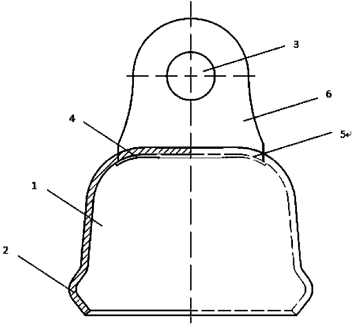
[0033] The first step is to use 235 steel plates to cut off the cylinder material and the traction hanging button material respectively;

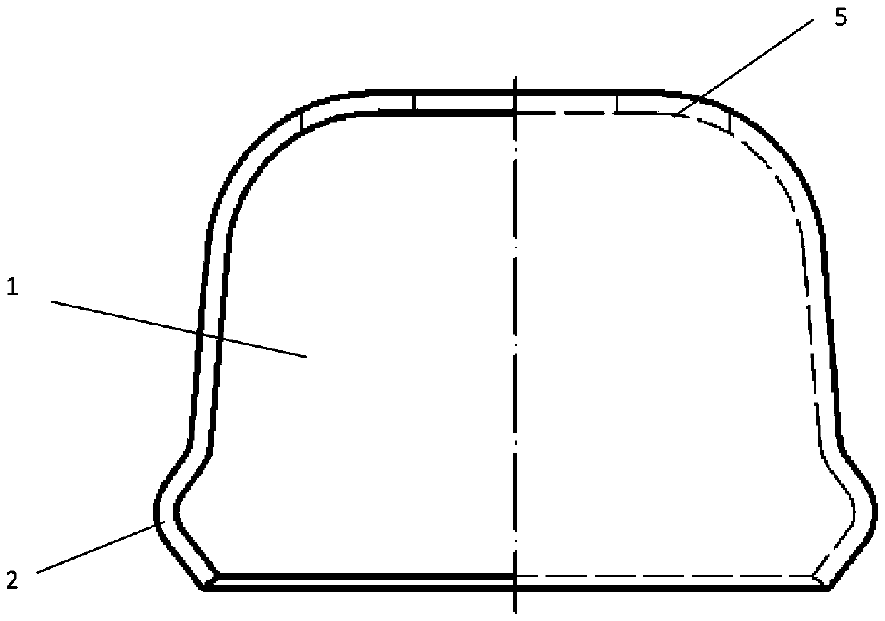
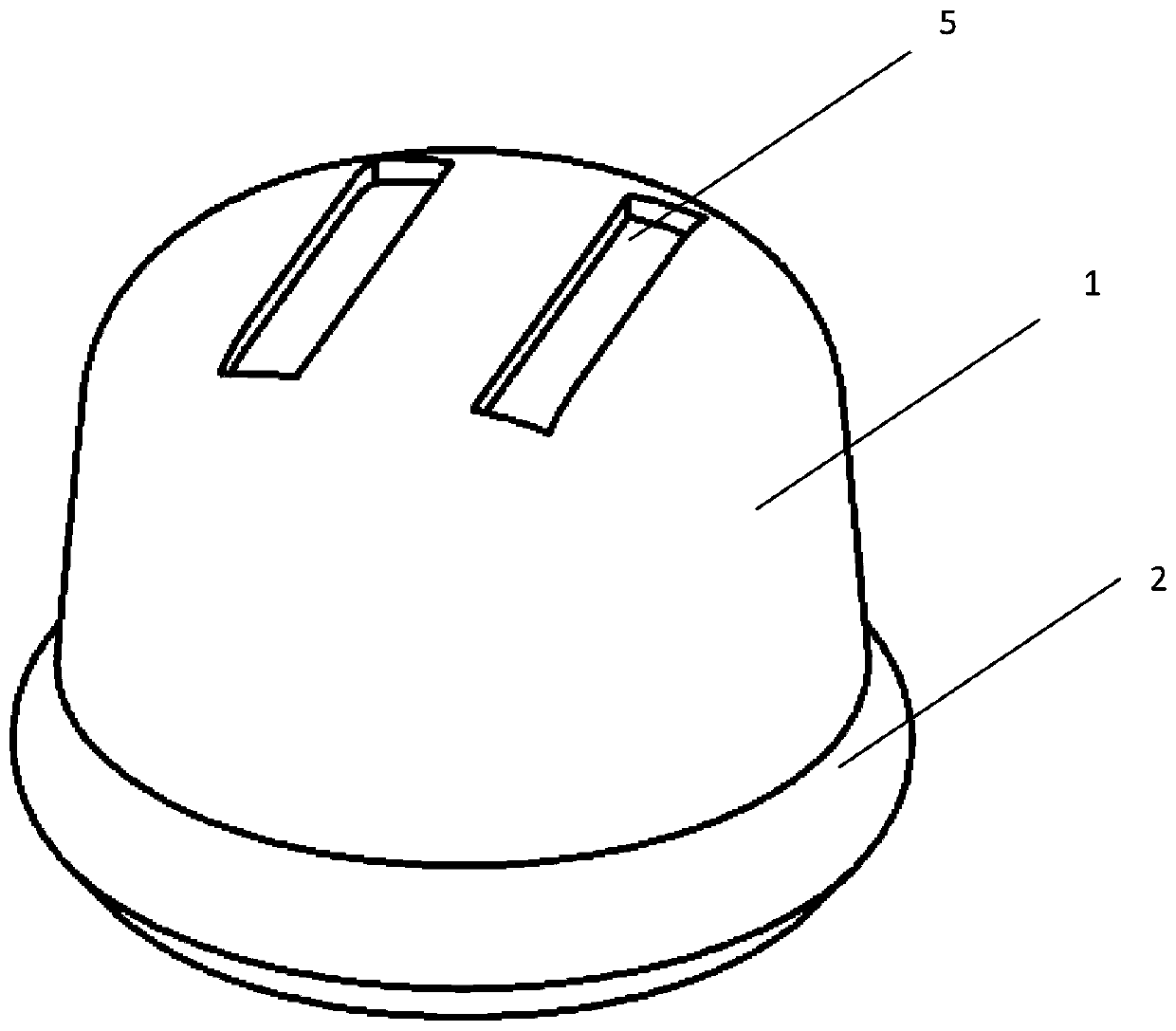
[0034] In the second step, put the cut material into a stamping machine dedicated to the thermal shock method for stamping; the traction hook 6 is punched and formed at one time, and when the traction hanger 6 is inserted into the groove from the side of the cylinder body 1, the riveting foot Processed into "I" shape; cylinder body 1 is stamped twice; the first time is stamped into a stalactite-shaped cylinder blank, and at the same time, two grooves 5 are pressed out on the upper end of cylinder body 1; the second time is with a special arc-expanding stamping device Stamping the lower end of the cylinder so that the lower end of the cylinder forms a circular arc dimple 2;

[0035] The third step is to assemble the stamped cylinder 1 and the traction hook 6; firstly, ...


PUM


Abstract

The invention discloses an insulator steel cap and a manufacturing method. The insulator steel cap is composed of two traction hanging buttons 6 and a cylinder body 1, wherein an upper end of each traction hanging button 6 is provided with a traction hanging hole 3, a lower end of each traction hanging button 6 is provided with riveting feet 4, a steel cap cylinder body 1 is stalactitic, an upperend of the cylinder body 1 is provided with two grooves 5 for installing and fixing the riveting feet 4 of the traction hanging buttons 6, a lower end of the cylinder body is a nest groove to preventthe rainwater from overflowing into an insulator. The part machining method is stamping manufacturing. The method is advantaged in that firstly, the weight is light, product quality standards are unified, the standard percent of pass can reach 99.9%, the process is simple, energy consumption is low, and the environment is not polluted; and secondly, potential safety hazards can be prevented, the rainwater cannot overflow into the insulator, and the product is long in service life, large in traction force, free of breakage and capable of being widely applied to assembly of insulators.

Description

technical field [0001] The invention relates to accessories and production of an insulator, in particular to a steel cap for an electric porcelain insulator and a production method. Background technique [0002] The steel cap of the electric porcelain insulator before the present invention is made by the method of casting, and the cylinder body of the steel cap and the pulling button are formed into one body by one-time casting. There are many deficiencies in this steel cap produced by the casting method. [0003] One is that there are many links in the processing technology, and the deviation of each link has an impact on the quality of the entire product, and then the quality of the operator and the mentality of the on-duty staff have an impact on the quality of the product; thus the product quality is unstable and the pass rate is low , a large waste; [0004] Second, due to the need to melt the steel produced, it consumes a lot of energy and pollutes the environment; ...

Claims


Application Information

Patent Timeline
IPC IPC(8): H01B17/40H01B19/00
CPCH01B17/40H01B19/00
Inventor 陈启军申自强陈志银
Owner 陈启军
Features
  • Generate Ideas
  • Intellectual Property
  • Life Sciences
  • Materials
  • Tech Scout
  • Unparalleled Data Quality
  • Higher Quality Content
  • 60% Fewer Hallucinations
Learn More