A new preparation process of busbar based on igbt module

A preparation process and busbar technology, applied in the field of new busbar preparation technology, can solve the problems of reducing the cleaning pressure of the subsequent process, reducing the amount of solder paste, reducing the cost and assembly, etc., achieving high market promotion value, reducing cleaning pressure, The effect of stable welding

Active Publication Date: 2021-03-16
宜兴市三鑫电子有限公司
View PDF6 Cites 0 Cited by
  • Summary
  • Abstract
  • Description
  • Claims
  • Application Information

AI Technical Summary

Problems solved by technology

[0009] Aiming at the problems existing in the prior art, the purpose of the present invention is to provide a new preparation process for busbars based on IGBT modules, which can realize the abandonment of traditional pad forms when performing electronic components such as busbars and electrodes, Using a new type of positioning cylinder, through the pre-designed extended conductive parts, on the one hand, it can realize stable electrical connection, on the other hand, it can replace the existing tooling to realize the initial positioning function, and directly enter the welding process after dripping solder paste. Significantly reduce the cost and cumbersomeness of assembly, and the amount of solder paste used is greatly reduced compared with the traditional process. Only a very small amount of solder paste needs to be dropped into the positioning cylinder to achieve accurate and stable welding, thereby reducing the cleaning pressure of subsequent processes , and even reach the point of no-cleaning under the condition of strict control of the dropping amount, the IGBT module prepared by the new process has unparalleled advantages in cost and efficiency, and avoids many factors that affect product quality, and has a very high marketing value

Method used


Image

  • A new preparation process of busbar based on igbt module
  • A new preparation process of busbar based on igbt module
  • A new preparation process of busbar based on igbt module

Examples


Embodiment 1

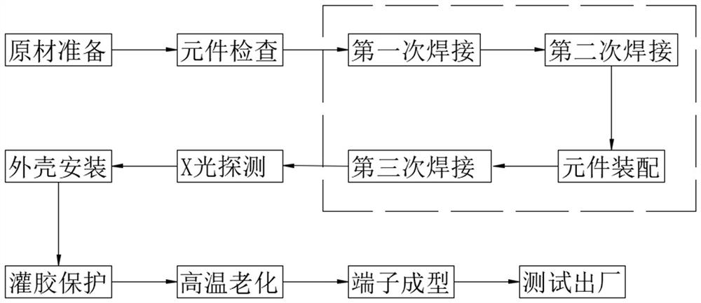
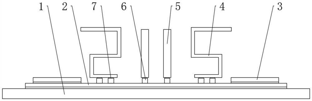
[0049] see figure 2 , a new preparation process of busbar 5 based on IGBT module. The IGBT module includes a liner 2, a substrate 1, a busbar 5, electrodes 4, semiconductor chips 3 and a casing, and a plurality of positioning cylinders 6 are fixedly connected to the liner 2. The positioning cylinder 6 innovatively replaces the traditional soldering pads. The traditional soldering pads can only achieve good electrical contact and do not have the positioning effect of the tooling. Moreover, the processing of the soldering pads is more difficult than the positioning cylinder 6. It is difficult for technicians. The technical requirement is higher, and the height of the positioning cylinder 6 in this embodiment is 5 mm, and a cylindrical hole is drilled in the positioning cylinder 6 to improve the space for accommodating electrical connections. The shape of the cylindrical hole can be set by the technician according to the actual situation, and It can be cylindrical or square, and...


PUM


Abstract

The invention discloses a novel manufacturing process of a busbar based on an IGBT module. When electronic components such as a busbar, an electrode and the like are adopted, a traditional bonding padform is abandoned. A novel positioning cylinder form is adopted. Through a pre-designed extended conductive component, on one hand, stable electrical connection is realized; on the other hand, an existing tool can be replaced to achieve an initial positioning effect. After a soldering paste is dropwise added, a welding procedure is directly performed. Cost and the assembling complexity are greatly reduced, an amount of the used soldering paste is greatly reduced compared with that in a traditional process, accurate and stable welding can be achieved only by dropwise adding a very small amountof soldering paste into a positioning cylinder, then cleaning pressure of a subsequent process is reduced, and even a cleaning-free state is achieved under a condition that a dropwise adding amount is strictly controlled. The IGBT module manufactured by adopting the novel process has incomparable advantages in cost and efficiency, many factors influencing product quality are avoided, and an extremely high market promotion value is possessed.

Description

technical field [0001] The invention relates to the technical field of semiconductor manufacturing, and more specifically, relates to a novel preparation process for a busbar based on an IGBT module. Background technique [0002] IGBT (Insulated Gate Bipolar Transistor), Insulated Gate Bipolar Transistor, is a composite fully-controlled voltage-driven power semiconductor device composed of BJT (Bipolar Transistor) and MOS (Insulated Gate Field Effect Transistor), with MOSFET The advantages of high input impedance and low conduction voltage drop of GTR. The saturation voltage of GTR is low, the carrying current density is large, but the driving current is large; the driving power of MOSFET is small, the switching speed is fast, but the conduction voltage drop is large, and the current carrying density is small. The IGBT combines the advantages of the above two devices, with low driving power and low saturation voltage. It is very suitable for the conversion system with a DC...

Claims


Application Information

Patent Timeline
Patent Type & Authority Patents(China)
IPC IPC(8): H01L21/50H01L21/60
CPCH01L21/50H01L24/80H01L2224/80213H01L2224/80345
Inventor 宗荣生戴赟彬白艳侯广西蒋超
Owner 宜兴市三鑫电子有限公司
Why Eureka
Try Eureka