A kind of SAR imaging method and system

An imaging method and azimuth technology, applied in radio wave measurement systems, instruments, measuring devices, etc., can solve problems affecting imaging effects, low algorithm calculation accuracy, and real-time performance, so as to simplify processing time and improve computing efficiency , Improving the effect of imaging accuracy

Active Publication Date: 2021-06-15
NANJING UNIV OF AERONAUTICS & ASTRONAUTICS
View PDF6 Cites 1 Cited by
  • Summary
  • Abstract
  • Description
  • Claims
  • Application Information

AI Technical Summary

Problems solved by technology

The distance Doppler algorithm, Chirp Scaling algorithm, and polar coordinate format algorithm are not easy to implement on hardware, and the real-time performance is poor; the traditional PFA algorithm realizes two-dimensional data resampling through two-dimensional interpolation and two-dimensional FFT, which is easy to implement on hardware. However, the two-dimensional interpolation calculation is huge, the resource utilization rate on the chip is not high, the calculation processing time is long, the system cannot meet the real-time requirements, and the calculation accuracy of the algorithm is not high. Moreover, the micro SAR platform will be affected by the actual flight activities. Due to the influence of external factors such as airflow disturbance, there is an error between the flight trajectory and the ideal trajectory, resulting in distortion and defocus of the PFA imaging results, which will also affect the final imaging effect
[0005] To sum up, the existing SAR imaging methods have the defects of low computing efficiency, poor real-time performance, and low imaging accuracy.

Method used


Image

  • A kind of SAR imaging method and system
  • A kind of SAR imaging method and system
  • A kind of SAR imaging method and system

Examples


Embodiment 1

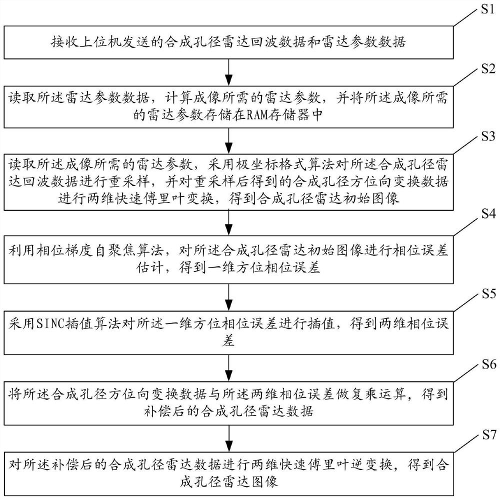
[0072] figure 1 It is a flowchart of a SAR imaging method according to Embodiment 1 of the present invention.

[0073] see figure 1 , the FPGA-based SAR imaging method of the embodiment, comprising:

[0074] Step S1: Receive the SAR echo data and radar parameter data sent by the host computer.

[0075] The synthetic aperture radar echo data is stored in the DDR3 memory built in the FPGA chip; the radar parameter data is stored in the REG register built in the FPGA chip.

[0076] Step S2: Read the radar parameter data, calculate the radar parameters required for imaging, and store the radar parameters required for imaging in a RAM memory.

[0077] In the step S2, the radar parameter data includes: aircraft flight angle θ, distance to time axis t τ , range interpolation frequency axis f x , distance to scale transform frequency axis f τ , the coordinates of the initial position of the aircraft, the distance OC from the initial position of the radar to the center of the sce...

Embodiment 2

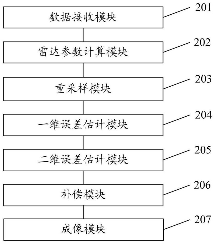
[0119] figure 2 It is a schematic structural diagram of a SAR imaging system according to Embodiment 2 of the present invention. see figure 2 , the FPGA-based SAR imaging system of the embodiment, comprising:

[0120] The data receiving module 201 is used to receive the SAR echo data and radar parameter data sent by the host computer; the SAR echo data is stored in the built-in DDR3 memory of the FPGA chip; the radar parameter data is stored in the In the REG register built in the FPGA chip.

[0121] The radar parameter calculation module 202 is configured to read the radar parameter data, calculate the radar parameters required for imaging, and store the radar parameters required for imaging in a RAM memory.

[0122] The resampling module 203 is used to read the radar parameters required for the imaging, use a polar coordinate format algorithm to resample the synthetic aperture radar echo data, and perform resampling on the synthetic aperture azimuth transformation data ...

Embodiment 3

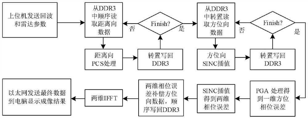
[0145] image 3 It is a flow chart of the FPGA-based SAR imaging method in Embodiment 3 of the present invention; Figure 4 It is a block diagram of FPGA hardware implementation in Embodiment 3 of the present invention. see image 3 and Figure 4 , the FPGA-based SAR imaging system provided in this embodiment implements the following steps.

[0146]Step 1: Send micro SAR echo data with a size of 4k*2k single-precision floating-point complex numbers and radar parameter data with a format of 64-bit double-precision complex numbers to the FPGA development board through the host computer and Ethernet interface. Micro SAR echo data is stored in the built-in DDR3 memory of the FPGA chip, and radar parameter data is stored in the REG register built in the FPGA chip. Micro SAR echo data is stored in the form of 4096 rows and 2048 columns; the column data is the data in the range direction, and the row data is the data in the azimuth direction.

[0147] Step 2: Read the radar para...


PUM


Abstract

The invention discloses a SAR imaging method and system. The method includes: receiving SAR echo data and radar parameter data sent by a host computer; calculating radar parameters required for imaging; resampling the SAR echo data by using a polar coordinate format algorithm; resampling the resampled data Perform two-dimensional fast Fourier transform to obtain the initial image of the synthetic aperture radar; use the phase gradient self-focusing algorithm to estimate the phase error of the initial image of the synthetic aperture radar to obtain the one-dimensional azimuth phase error; use the SINC interpolation algorithm to calculate the one-dimensional azimuth phase The error is interpolated to obtain the two-dimensional phase error; the resampled data is multiplied by the two-dimensional phase error to obtain the compensated SAR data; the two-dimensional fast Fourier transform is performed on the compensated SAR data Inverse transform to get the synthetic aperture radar image. The invention can realize fast real-time imaging of SAR, and improves computing efficiency and imaging accuracy.

Description

technical field [0001] The invention relates to the technical field of radar imaging, in particular to a SAR imaging method and system. Background technique [0002] Synthetic Aperture Radar (SAR) uses the movement of a single antenna element to correlate and synthesize the acquired echo signals to form a complete array, and uses signal processing technology to perform high-resolution imaging of scene targets. Different from traditional optical imaging and infrared remote sensing, SAR can work normally without being affected by complex meteorological conditions and extraordinary time periods, and has the characteristics of high resolution and large width. Initially, SAR was mainly used on airborne, spaceborne, and missile-borne platforms. With the development of small unmanned aerial vehicles, it has gradually become a research hotspot to carry micro-SAR imaging systems on them. [0003] The SAR imaging algorithm is complex, and the amount of data processing is large. In or...

Claims


Application Information

Patent Timeline
Patent Type & Authority Patents(China)
IPC IPC(8): G01S13/90
CPCG01S13/90G01S13/9004
Inventor 朱岱寅刘芮王蝶杜婉婉
Owner NANJING UNIV OF AERONAUTICS & ASTRONAUTICS
Why Eureka
Try Eureka