MBR (membrane bioreactor) membrane aerator, MBR membrane aeration device and MBR membrane sewage treatment equipment

A technology of membrane aeration and air flow, applied in biological water/sewage treatment, water/sludge/sewage treatment, aerobic process treatment, etc., can solve problems such as aeration pipe blockage, and achieve low loss and small pressure loss Effect

Pending Publication Date: 2019-12-13
嘉兴市聚元环保科技有限公司
View PDF0 Cites 1 Cited by
  • Summary
  • Abstract
  • Description
  • Claims
  • Application Information

AI Technical Summary

Problems solved by technology

However, when the sludge concentration or viscosity is high, the aeration pipe is prone to clogging. It is necessary to adjust the cleaning frequency and procedure according to the situation. When the clogging is serious, it needs to be lifted out of the tank for cleaning.

Method used


Image

  • MBR (membrane bioreactor) membrane aerator, MBR membrane aeration device and MBR membrane sewage treatment equipment
  • MBR (membrane bioreactor) membrane aerator, MBR membrane aeration device and MBR membrane sewage treatment equipment
  • MBR (membrane bioreactor) membrane aerator, MBR membrane aeration device and MBR membrane sewage treatment equipment

Examples


Embodiment 1

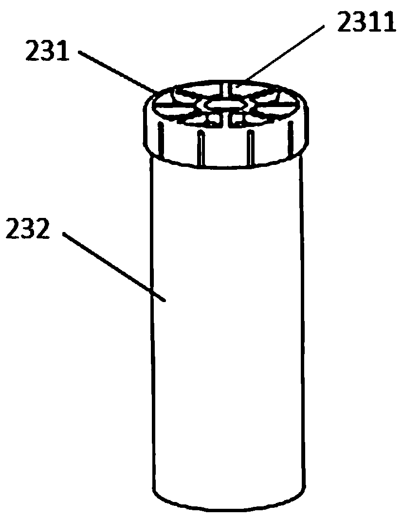
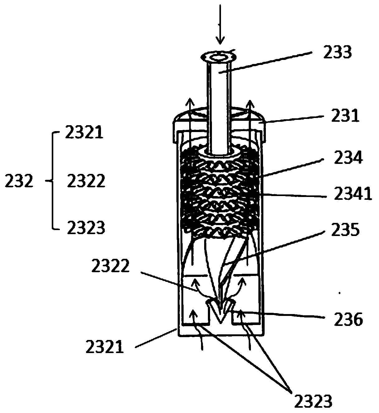
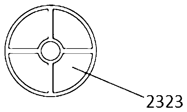
[0035] see Figure 1 to Figure 3 as shown, figure 1 It is a schematic diagram of the appearance of the MBR membrane aerator, figure 2 It is the internal structure diagram of the MBR membrane aerator, image 3 It is a bottom view of the MBR membrane aerator, and the present invention provides an MBR membrane aerator, which includes a top cover 231, the upper end of the top cover 231 has a through mixed liquid outlet 2311; a body 232, including an outer shell 2321 with an open top and the mixing cavity 2322, the mixing cavity 2322 is located in the outer shell 2321, the top cover 231 is buckled on the upper end of the outer shell 2321, and the bottom end of the body 232 is provided with a mixed liquid that communicates the mixing cavity 2322 with the outside of the body 232 Inlet 2323, alternatively, in this embodiment, the bottom end of the body 232 is open, and the bottom end of the body 232 adopts the same matching structure as the top cover 231, and a hollow bottom is buc...

Embodiment 2

[0042] Such as Figure 4 as shown, Figure 4 It is a schematic diagram of an MBR membrane aeration device. Based on the same inventive concept, the present invention also provides a MBR membrane aeration device, including a central air delivery pipe 21; several air delivery branch pipes 22, and the gas delivery branch pipes 22 are arranged on the central air delivery pipe 21, the gas delivery branch pipe 22 includes a main pipe 221 and several branch pipes 222. The top of the branch pipe 222 communicates with the main pipe 221. Vertically intersect and communicate with each other on the same horizontal plane, and several gas delivery branch pipes 22 are arranged in parallel; several MBR membrane aerators 23 described in Embodiment 1, the number of MBR membrane aerators 23 corresponds to the number of branch pipes 222 , the bottom end of the branch pipe 222 is connected to the top of the air pipe 233 in the MBR membrane aerator 23. In this embodiment, the bottom end of the bra...

Embodiment 3

[0046] Such as Figure 5 as shown, Figure 5 It is MBR membrane sewage treatment equipment, based on the same inventive concept, the present invention also provides a kind of MBR membrane sewage treatment equipment, including fan 1, the MBR membrane aeration device 2 described in Embodiment 2, membrane pool 3 and MBR membrane module 4. The air outlet of the fan 1 is connected to the air inlet of the central air pipe 21 , the MBR membrane module 4 is set in the membrane tank 3 , and the MBR membrane aeration device 2 is set in the lower part of the MBR membrane module 4 .


PUM


Abstract

The invention discloses an MBR membrane aerator. The MBR membrane aerator comprises a top cover, a body, an air pipeline, a rotary cutting column, a guide plate and an airflow backwashing mechanism, the air pipeline is inserted into an inner mixing cavity from the top end of the top cover, air in the air pipeline is input from top to bottom, the problem of blockage of the air pipeline can be effectively solved, the problem of blockage of aeration equipment can be solved even the aerator works at high sludge concentration, and daily maintenance is not required; and meanwhile, air forms rising flow after entering the aerator under the action of the airflow backwashing mechanism to drive a mud and water mixed solution to upwards rapidly rushing out of the top of the aerator together to realize aeration washing of an MBR membrane, the rotary cutting column and the guide plate mounted in the body can rotate the mixed solution, the mixed solution is cut by cutting blades in the rotating rising process to form a large number of tiny bubbles, and the aeration washing effect is improved. The invention also discloses an MBR membrane aeration device comprising the MBR membrane aerator and MBRmembrane sewage treatment equipment.

Description

technical field [0001] The invention belongs to the field of sewage treatment, and in particular relates to an MBR membrane aerator, an MBR membrane aeration device and MBR membrane sewage treatment equipment. Background technique [0002] MBR (Membrane Bioreactor) process is a new water treatment technology that combines activated sludge process and membrane separation technology. According to the structural type of the membrane, there are flat type, tubular type, spiral type and hollow fiber type. Flat membrane or hollow fiber membrane modules need to be aerated at the bottom of the membrane module during operation. In addition to the basic function of supplying oxygen to the microorganisms in the bioreactor, the membrane module aeration system is also an effective means to control membrane fouling. By using the gas-liquid two-phase flow generated by the aeration at the lower part of the membrane module to provide scour on the membrane surface, the sludge adsorbed on the...

Claims


Application Information

Patent Timeline
Patent Type & Authority Applications(China)
IPC IPC(8): C02F3/12C02F3/20
CPCC02F3/1268C02F3/208C02F2203/006Y02W10/10
Inventor 张东曙邱立俊李文贞
Owner 嘉兴市聚元环保科技有限公司
Why Eureka
Try Eureka