
Aerodynamics-based spontaneous device for catching water from air

An aerodynamic and spontaneous technology, applied in water supply devices, drinking water devices, buildings, etc., can solve problems such as difficult survival, accelerated water supply system aging, limited application range, etc., to achieve real-time and uninterrupted water replenishment, and improve vegetation Survival rate, effect of increasing soil moisture

Inactive Publication Date: 2019-12-13
QINGDAO TECHNOLOGICAL UNIVERSITY
View PDF0 Cites 1 Cited by
  • Summary
  • Abstract
  • Description
  • Claims
  • Application Information

AI Technical Summary

Problems solved by technology

However, many islands are far from land and lack fresh water resources, making it difficult to survive
The inventor found that the existing water replenishment devices have some disadvantages, such as high cost, high energy consumption, increased greenhouse gas emissions, and accelerated aging of the water supply system, etc.
The surface cooling air condensation method is a feasible method to produce fresh water, but the current water inlet device still has problems such as limited application range, small water output, and high energy consumption, and has not been widely used.
Desalination plants in coastal areas are bulky and costly and difficult to build
At the same time, in arid areas, the surface temperature is high, and the air humidity is high in the morning and night, but the absorption rate of vegetation is too low, and most of the water is lost due to evaporation.
In island areas where fresh water is scarce, the air humidity is high (about 80%), but fresh water resources are scarce

Method used


Image

  • Aerodynamics-based spontaneous device for catching water from air
  • Aerodynamics-based spontaneous device for catching water from air
  • Aerodynamics-based spontaneous device for catching water from air

Examples


Embodiment 1

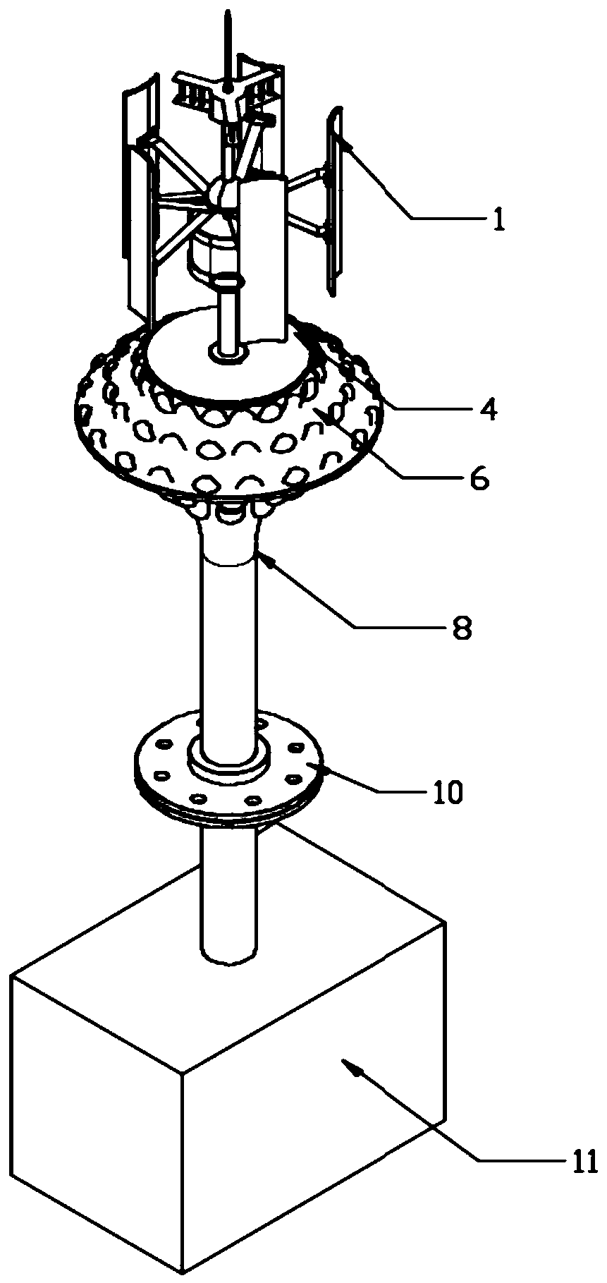
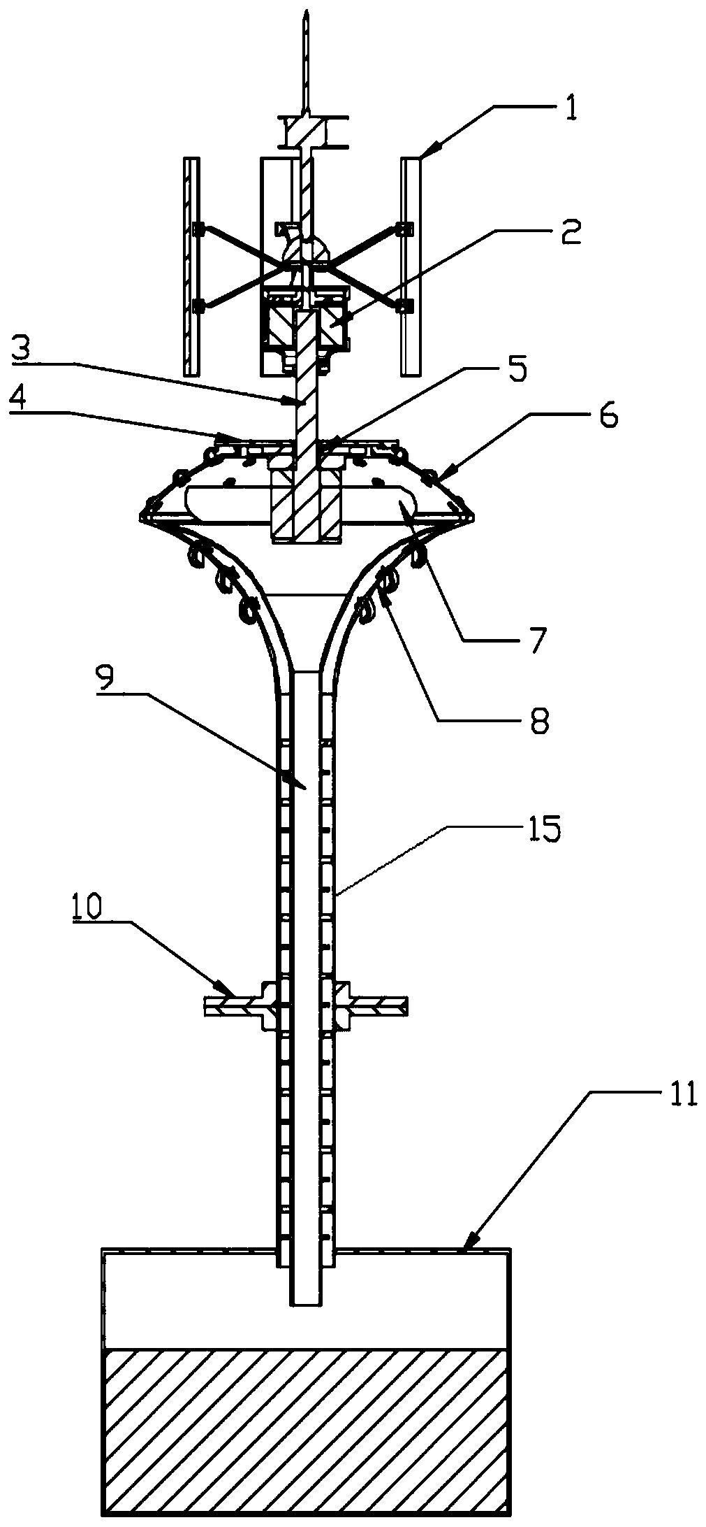
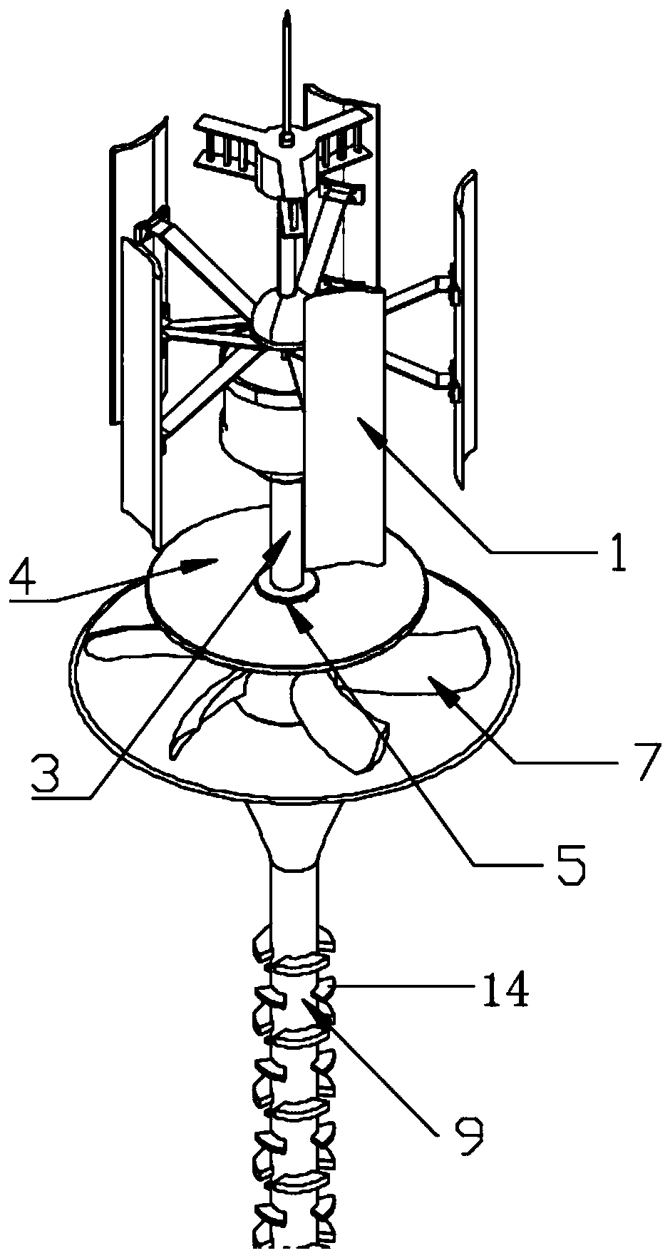
[0036] Attached below Figure 1-Figure 5 The present invention is described in detail, specifically, the structure is as follows:

[0037] This embodiment provides an aerodynamic self-generating air water capture device, including a wind cycle device, a water energy capture device, a housing and a support body 15, wherein the housing is installed above the support body 15, and the water energy capture device Installed inside the casing, the wind circulation device is rotatably connected to the top of the casing. When in use, the lower half of the device is buried in the ground, and the wind circulation device is driven by natural wind. Under the action of natural wind, water vapor enters the water energy capture device and is converted into liquid water in the water vapor capture device.

[0038] The casing includes an upper casing 6 and a lower casing 8, the upper casing 6 is installed above the lower casing 8, the upper casing 6 and the lower casing 8 have circular arc surf...


PUM


Abstract

The invention discloses an aerodynamics-based spontaneous device for catching water from air, and the device solves the problem that water resources cannot be efficiently utilized in the prior art, and has the effects of being capable of catching the water by natural wind and temperature difference and being low in cost and high in efficiency and having no pollution. According to the technical scheme, the device comprises a wind circulating device and a water energy catching device; the wind circulating device includes a lift-type blade set; the water energy catching device comprises wind circulating blades connected with the lift-type blade set and arranged in a shell; a condensation pipeline is connected below the wind circulating blades; the shell is provided with gas flowing holes; under the wind action, the lift-type blade set is capable of driving the wind circulating blades to rotate, and the air enters the shell under the double dynamic of pressure difference and the rotation of the wind circulating blades; and after being condensed by the condensation pipeline, steam in the air can be collected by a collecting water tank fixed to the lower end of the condensation pipeline.

Description

technical field [0001] The invention relates to the technical field of water-saving irrigation, in particular to an aerodynamic-based self-generating air water catcher. Background technique [0002] The air catcher is one of the effective methods to solve the shortage of fresh water resources in special places. Our country has a vast ocean territory and many islands. However, many islands are far from land and lack fresh water resources, making it difficult to survive. The inventors found that the existing water replenishment device has some disadvantages, such as high cost, high energy consumption, increased emission of greenhouse gases, and accelerated aging of the water supply system. The surface cooling air condensation method is a feasible method for producing fresh water, but the current water inlet device still has problems such as limited application range, small water output, and high energy consumption, and has not been widely used. Desalination plants in coastal...

Claims


Application Information

Patent Timeline
IPC IPC(8): E03B3/28
CPCE03B3/28
Inventor 刘庆玉樊泞歌宋岩卓田野邢博源姬一鸣吕宗凯孟岩
Owner QINGDAO TECHNOLOGICAL UNIVERSITY
Learn More