Hydrogen circulating pump assembly

A technology of hydrogen circulation and assembly, applied in pumps, pump components, rotary piston pumps, etc., can solve the problems of hydrogen embrittlement and hydrogen corrosion, increase the oil content of the output hydrogen, leakage, etc., to prolong the service life, ensure the sealing effect, The effect of improving safety

Pending Publication Date: 2019-12-13
YANTAI DONGDE IND CO LTD
View PDF0 Cites 10 Cited by
  • Summary
  • Abstract
  • Description
  • Claims
  • Application Information

AI Technical Summary

Problems solved by technology

However, the existing air compressors have poor sealing of the overall structure, and hydrogen is not only easy to leak from the gap, but also the lubricating oil in the gear chamber has the risk of lubricating oil leakage during the process of pressurizing hydrogen in the air compressor. , after the lubricating oil leaks from the gear chamber to the compression chamber, it will be mixed into the hydrogen gas driven by the high-pressure gas, increasing the oil content of the output hydrogen gas, resulting in the danger of fuel cell stack poisoning; moreover, the internal structure of the existing air compressor And the material cannot resist hydrogen corrosion, which will cause hydrogen embrittlement and hydrogen corrosion, which will affect the service life of the air compressor

Method used


Image

  • Hydrogen circulating pump assembly
  • Hydrogen circulating pump assembly
  • Hydrogen circulating pump assembly

Examples


Embodiment 1

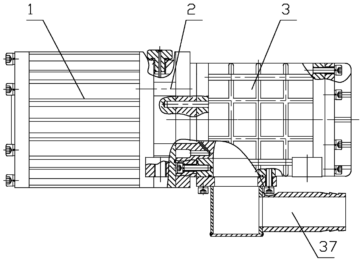
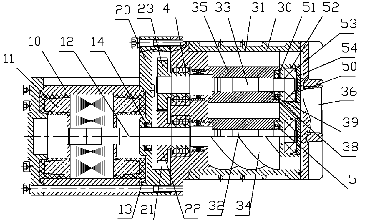
[0041] Such as figure 1 , 2 , 3, a hydrogen circulation pump assembly includes a motor part 1, a gear chamber part 2 and a supercharger part 3, the gear chamber part 2 is arranged between the motor part 1 and the supercharger part 3, and the motor Part 1 includes a motor housing 10, a motor 11, and a motor main shaft 12. The gear chamber part 2 includes a gear chamber housing 20, a gear chamber 21, a driving gear 22, and a driven gear 23. The supercharger part 3 includes Supercharger housing 30, compression chamber 31, male rotor shaft 32, female rotor shaft 33, male rotor 34, female rotor 35, air inlet 36 and air outlet 37,

[0042] Between the motor housing 10 and the gear chamber housing 20, between the gear chamber housing 20 and the supercharger housing 30, a sealing ring 13 is provided for sealing, so as to avoid hydrogen leakage from the gap;

[0043] A motor oil seal 14 is provided between the motor main shaft 12 and the gear chamber housing 20; a first sealing struc...

Embodiment 2

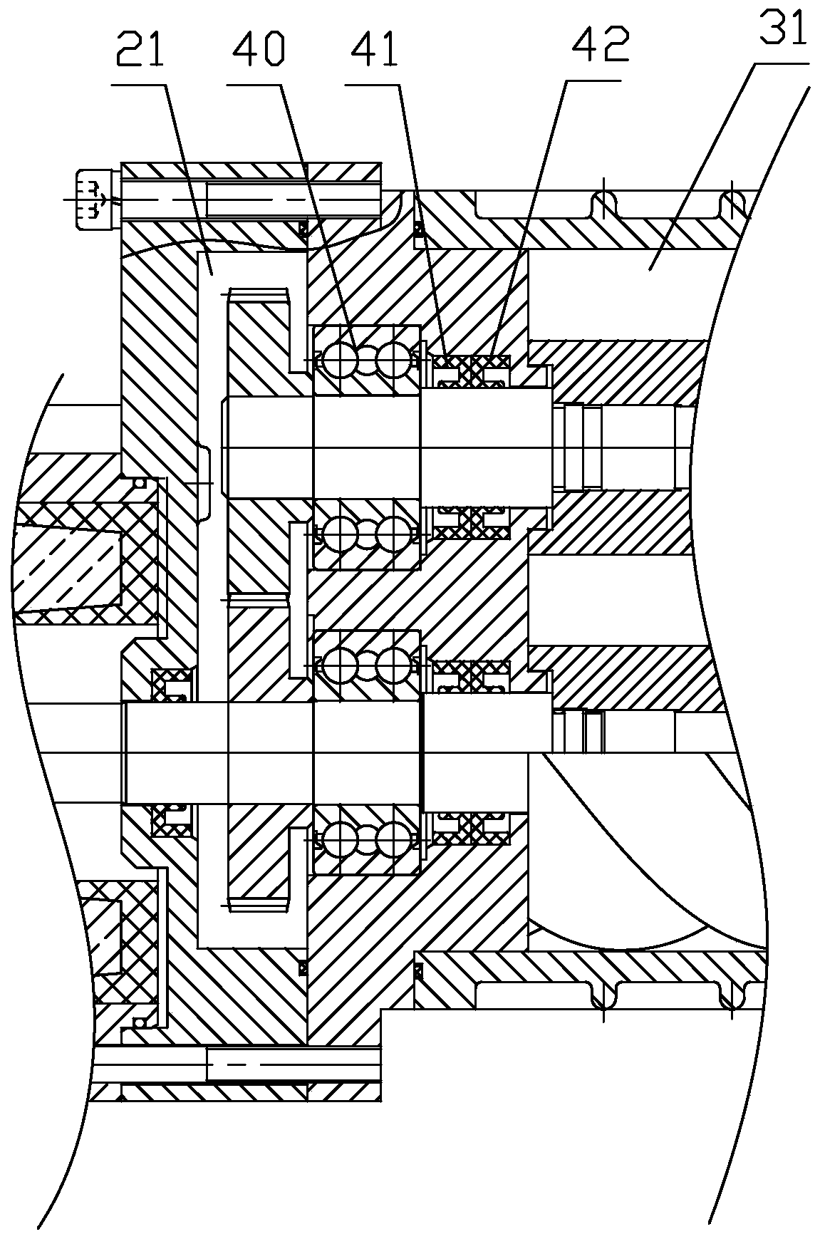
[0048] Such as figure 1 , 2 , 4, and 5, the difference between this embodiment and embodiment 1 is that the first sealing structure 4 includes a rolling bearing 43, an oil baffle 44, a first oil seal 41, a second oil seal 45 and an air seal 42 arranged in sequence, The rolling bearing 43 is close to the gear chamber 21, the air seal 42 is close to the compression chamber 31, an oil chamber 46 is provided between the first oil seal 41 and the oil baffle plate 44, and the oil chamber 46 passes through the oil provided in the gear chamber housing 20. The hole 47 communicates with the gear chamber 21 ; the oil baffle 44 is in interference fit with the gear chamber housing 20 , and the oil baffle 44 is in clearance fit with the male rotor shaft 32 and the female rotor shaft 33 . The second oil seal 45 and the air seal 42 are spaced apart, and the cavity between the second oil seal 45 and the air seal 42 communicates with the outside world through the vent hole 48 provided in the g...


PUM


Abstract

The invention provides a hydrogen circulating pump assembly. Sealing rings are arranged between a motor shell and a gear chamber shell as well as between the gear chamber shell and a pressurizer shellto perform sealing; motor oil seal is arranged between the motor main shaft and the gear chamber shell; first sealing structures are arranged between a positive rotor shaft and the gear chamber shellas well as between a negative rotor shaft and the gear chamber shell; second sealing structures are arranged between the positive rotor shaft and the pressurizer shell as well as between the negativerotor shaft and the pressurizer shell; a ceramic coating is arranged on the inner wall of the pressurizer shell; a positive rotor and a negative rotor are provided with polytetrafluoroethylene coatings; and the motor is an explosion-proof motor. The hydrogen circulating pump assembly prevents hydrogen from leaking from gap to the outside, also prevents the hydrogen from leaking from a compressioncavity to the directions of a gear chamber and the motor, improves safety, effectively prevents lubricating oil in the gear chamber from leaking into the compression cavity, greatly reduces the oil content of the hydrogen after output and avoids the poisoning phenomenon of a fuel cell stack; in addition, internal parts are subjected to coating treatment, so hydrogen embrittlement and hydrogen corrosion are avoided and the service life is prolonged.

Description

Technical field: [0001] The invention relates to a hydrogen circulation pump assembly. Background technique: [0002] Fuel cells generate electrical energy through the electrochemical reaction between combustible substances (hydrogen) and oxygen in the air. After the fuel cell reacts, the exhaust gas contains a large amount of hydrogen. If these hydrogen are directly discharged into the atmosphere, on the one hand It is a waste of energy. On the other hand, it causes pollution to the environment. Third, hydrogen is flammable and explosive and will cause danger. Therefore, it is necessary to recover and reuse these hydrogens. At present, the hydrogen is generally recycled back to the fuel cell through an air compressor for recycling. However, the existing air compressors have poor sealing of the overall structure, and hydrogen is not only easy to leak from the gap, but also the lubricating oil in the gear chamber has the risk of lubricating oil leakage during the process of...

Claims


Application Information

Patent Timeline
Patent Type & Authority Applications(China)
IPC IPC(8): F04C23/02F04C18/16F04C27/00F04C29/00F04C29/02H01M8/0662H01M8/04089
CPCF04C18/084F04C18/086F04C18/16F04C23/02F04C27/005F04C27/009F04C29/005F04C29/02H01M8/04097H01M8/0662Y02E60/50
Inventor 邢子义王升科谢元豪王明张勤宇
Owner YANTAI DONGDE IND CO LTD
Why Eureka
Try Eureka