Phased array antenna based on continuously adjustable substrate integrated waveguide phase shifter

A substrate-integrated waveguide and phased array antenna technology, which is applied to waveguide devices, antennas, and devices that enable antennas to work in different bands at the same time, can solve the problems of increased size and complexity, small beam scanning range, and integration Low-level problems, to achieve the effect of increasing bandwidth and gain, saving plane area, and increasing phase shift angle

Inactive Publication Date: 2019-12-13
SHENZHEN UNIV
View PDF3 Cites 6 Cited by
  • Summary
  • Abstract
  • Description
  • Claims
  • Application Information

AI Technical Summary

Problems solved by technology

The disadvantage of the first method is that only a very limited number of discrete scan angles can be achieved, and its size and complexity will increase greatly as the required beam pointing requirements increase
In comparison, the second method is simpler to implement, but due to the large size of the existing traditional phase shifter, the low integration of the system is still a problem that needs to be solved
[0004] In the current published literature, some use a surface-mounted digital phase shifter to connect with the SIW slot antenna, which can only obtain a smaller discrete beam scanning range and a narrower bandwidth; some use an external digital phase shifter Phase shifters, external power dividers, coaxial cables, and control computers can be used to adjust the phase of the SIW slot antenna to obtain a larger sweep angle, but this solution has low integration, large system volume, and high cost; there is another The method is to use ferrite low-temperature co-fired ceramic (LTCC) technology combined with SIW technology to realize continuous adjustment of the phase of the antenna unit, and the system is small in size, but limited by the number of available LTCC layers, it is difficult to achieve large-angle scanning
[0005] The above-mentioned defects in various aspects will limit the application of these phased array antennas in 5G Wi-Fi systems

Method used


Image

  • Phased array antenna based on continuously adjustable substrate integrated waveguide phase shifter
  • Phased array antenna based on continuously adjustable substrate integrated waveguide phase shifter
  • Phased array antenna based on continuously adjustable substrate integrated waveguide phase shifter

Examples


Embodiment Construction

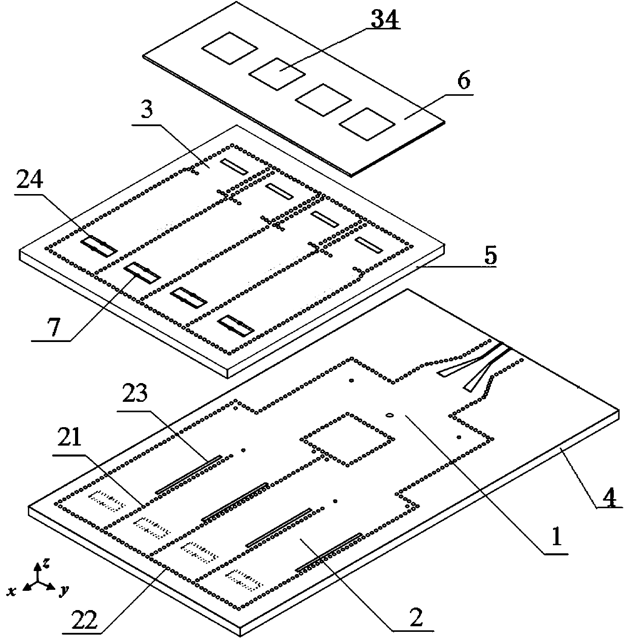
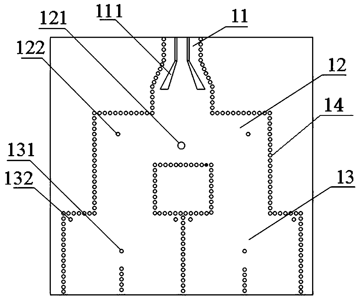
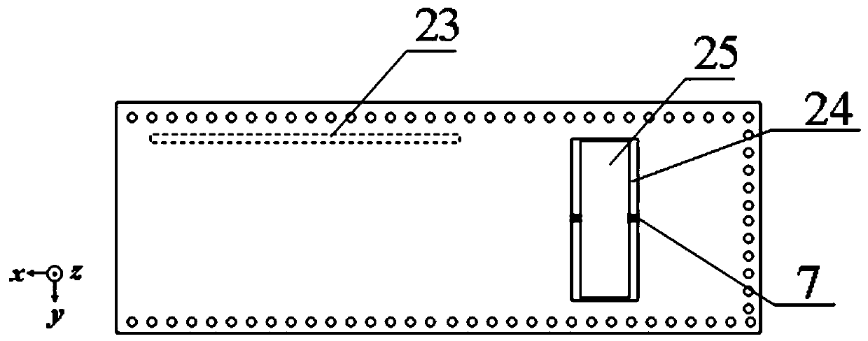
[0041] Embodiments of the present invention are described in detail below, examples of which are shown in the drawings, wherein the same or similar reference numerals designate the same or similar elements or elements having the same or similar functions throughout. The embodiments described below by referring to the figures are exemplary and are intended to explain the present invention and should not be construed as limiting the present invention.

[0042] In describing the present invention, it should be understood that the terms "length", "width", "upper", "lower", "front", "rear", "left", "right", "vertical", The orientation or positional relationship indicated by "horizontal", "top", "bottom", "inner", "outer", etc. are based on the orientation or positional relationship shown in the drawings, and are only for the convenience of describing the present invention and simplifying the description, rather than Nothing indicating or implying that a referenced device or element...


PUM


Abstract

The invention belongs to the technical field of wireless communication, and relates to a phased array antenna based on a continuously adjustable substrate integrated waveguide phase shifter. The phased array antenna comprises a feed network, a phase shifter and a radiation unit, wherein the feed network is connected between the phase shifter and the radiation unit; the feed network comprises a converter, a T-shaped power divider and a Y-shaped power divider; the output end of the converter is connected with the input end of the T-shaped power divider, the output ends of the T-shaped power divider are respectively connected with the input ends of the Y-shaped power divider, and the output end of the Y-shaped power divider is connected with the phase shifter. The antenna has the advantages of low cost, compact structure, high integration level and large continuous scanning angle range.

Description

technical field [0001] The invention belongs to the technical field of wireless communication, and relates to a phased array antenna based on a continuously adjustable substrate integrated waveguide phase shifter. Background technique [0002] In recent years, 5G Wi-Fi (covering the working frequency band 5.15-5.85GHz) technology based on the 802.11ac standard has attracted more and more attention. Compared with the previous generation, it has a higher data transmission rate and wider channel bandwidth. It is worth noting that beamforming phased array antennas can greatly improve the transmission efficiency and coverage of 5G Wi-Fi devices. However, traditional phased array antennas are usually constrained by the shortcomings of limited beam scanning range, high cost, large volume, and complex structure. Therefore, there is an urgent need to design a phased array antenna with low cost, compact structure, easy processing and integration, and capable of large-angle scanning. ...

Claims


Application Information

Patent Timeline
Patent Type & Authority Applications(China)
IPC IPC(8): H01Q23/00H01Q3/36H01Q5/50H01P1/18
CPCH01P1/182H01Q3/36H01Q5/50H01Q23/00
Inventor 葛磊季媛
Owner SHENZHEN UNIV
Why Eureka
Try Eureka