High-voltage DC fault recovery method based on commutation voltage phase detection

A high-voltage direct current, fault recovery technology, applied in the direction of voltage-only measurement, current/voltage measurement, power transmission AC network, etc., can solve the problem that the phase-locked loop cannot lock the phase in time, the trigger angle deviates from the command value, and the shutdown angle cannot be adjusted and other issues to achieve the effect of improving recovery performance, improving effectiveness, and being easy to implement

Active Publication Date: 2019-12-13
SOUTH CHINA UNIV OF TECH
View PDF10 Cites 10 Cited by
  • Summary
  • Abstract
  • Description
  • Claims
  • Application Information

AI Technical Summary

Problems solved by technology

[0003] The three-phase phase-locked loop commonly used in HVDC transmission is the synchronous rotating frame phase-locked loop (SRF-PLL). When the system is running in a steady state, the SRF-PLL can accurately track the phase of the AC voltage. At this time, the actual The firing angle is equal to the firing angle command output by the controller; when the AC system on the inverter side fails, the phase of the AC voltage may change rapidly due to the removal of the fault and the restoration of the transmission power, resulting in the failure of the phase-locked loop to perform phase-locking in time , so that the actual firing angle deviates from its command value
If the actual firing angle exceeds the command value of the controller in a short period of time, the fixed turn-off angle controller will not be able to adjust the turn-off angle in time, and the converter is likely to fail in subsequent commutation at this time

Method used


Image

  • High-voltage DC fault recovery method based on commutation voltage phase detection
  • High-voltage DC fault recovery method based on commutation voltage phase detection
  • High-voltage DC fault recovery method based on commutation voltage phase detection

Examples


Embodiment

[0054]A high-voltage DC fault recovery method based on commutation voltage phase detection can effectively improve the ability of the system to resist subsequent commutation failures after another fault, and improve system recovery performance.

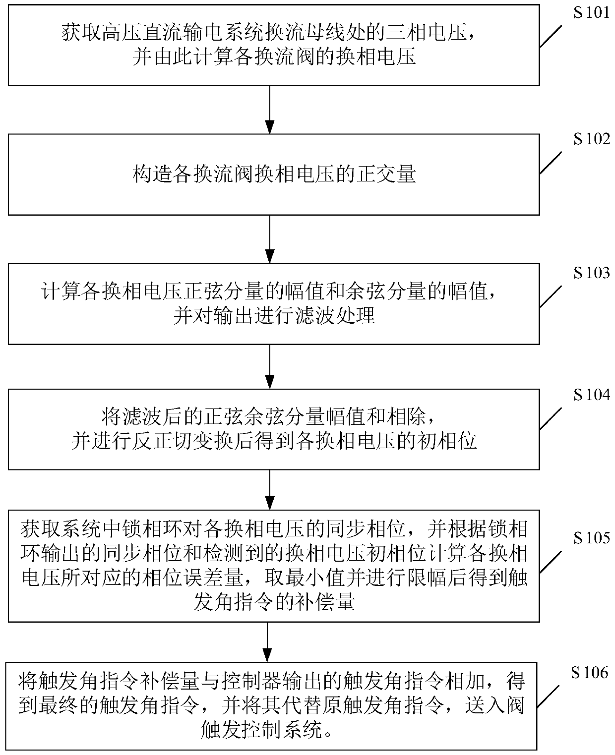
[0055] Such as figure 1 As shown, the method includes the following steps:

[0056] S101 obtains the instantaneous value of the three-phase voltage at the commutation bus of the HVDC power transmission system, and calculates the instantaneous value of the commutation voltage of each converter valve;

[0057] In this embodiment, the three-phase voltage at the converter bus in the HVDC power transmission system includes A-phase voltage, B-phase voltage and C-phase voltage. In the embodiment of the present invention, the phase A voltage is used as u A Indicates that the B-phase voltage adopts u B Indicates that the C-phase voltage adopts u C Indicates that the instantaneous value of the commutation voltage (line voltage) on the y sid...


PUM


Abstract

The invention discloses a high-voltage DC fault recovery method based on commutation voltage phase detection. According to the method, commutation voltage of each converter valve is calculated throughthree-phase voltage of a converter bus; an orthogonal quantity of each commutation voltage is constructed, amplitudes of a corresponding sine component and a cosine component are calculated by usingthe commutation voltages and the orthogonal quantities, and after filtering processing, the amplitudes of the sine component and the cosine component are divided, and arc tangent transformation is carried out to obtain an initial phase of the commutation voltages; a phase error of the phase-locked loop is calculated by using the synchronous phase outputted by the phase-locked loop and the detectedcommutation voltage initial phase, the minimum phase error amount corresponding to each commutation voltage and a trigger angle instruction value outputted by the controller are added, and a final trigger angle instruction is obtained. According to the method, the deviation between the actual trigger angle and the controller instruction under the fault can be effectively reduced, so that the effectiveness of the controller is improved, and the recovery performance of the system after the fault is improved.

Description

technical field [0001] The invention relates to the technical field of high voltage direct current, in particular to a high voltage direct current fault recovery method based on commutation voltage phase detection. Background technique [0002] In the DC transmission control system, the trigger phase control of the converter realizes the control of the DC transmission system and its converter operating state regulation by changing the trigger phase of the converter valve. In order to avoid the problem of harmonic instability, the current HVDC project generally adopts the equal-interval triggering technology, which generates equal-interval trigger pulse signal sequences according to the synchronous phase of the three-phase phase-locked loop, so as to realize the trigger phase control of the converter. [0003] The three-phase phase-locked loop commonly used in HVDC transmission is the synchronous rotating frame phase-locked loop (SRF-PLL). When the system is running in a stea...

Claims


Application Information

Patent Timeline
Patent Type & Authority Applications(China)
IPC IPC(8): H02J3/36G01R19/00G01R31/02
CPCH02J3/36G01R19/0084Y02E60/60
Inventor 汪娟娟文兆新龚英明丁天皓陈威
Owner SOUTH CHINA UNIV OF TECH
Why Eureka
Try Eureka