Amplitude modulation type radial polarization illumination confocal microimaging method and device

A confocal microscopic imaging and amplitude modulation technology, used in microscopes, optics, instruments, etc., can solve the problems of high processing accuracy and complex design process of binary optical components, achieve noise suppression, optimize confocal pinhole size, The effect of improving imaging resolution

Active Publication Date: 2019-12-17
哈工大机器人(中山)无人装备与人工智能研究院
View PDF5 Cites 3 Cited by
  • Summary
  • Abstract
  • Description
  • Claims
  • Application Information

AI Technical Summary

Problems solved by technology

However, the design process of binary optical elements is complex and requires high processing precision.

Method used


Image

  • Amplitude modulation type radial polarization illumination confocal microimaging method and device
  • Amplitude modulation type radial polarization illumination confocal microimaging method and device
  • Amplitude modulation type radial polarization illumination confocal microimaging method and device

Examples


Embodiment Construction

[0024] The implementation examples of the present invention will be described in detail below in conjunction with the accompanying drawings.

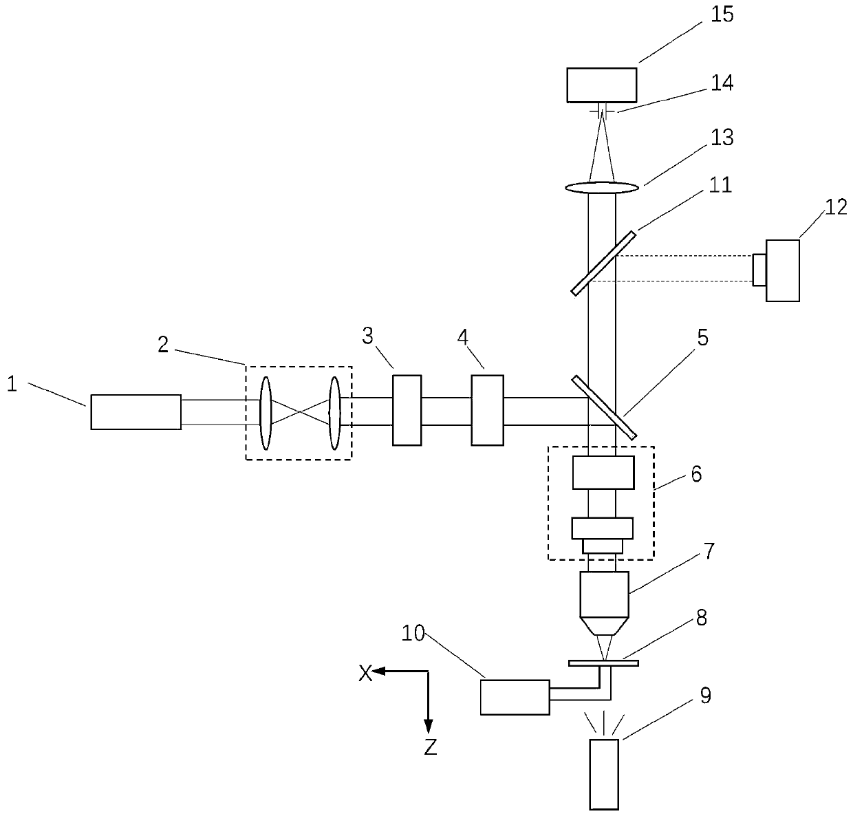
[0025] The schematic diagram of the amplitude-modulated radially polarized illumination confocal microscopy imaging method and device in this embodiment is as follows figure 1 shown. The linearly polarized laser light emitted by the laser 1 is shaped and expanded by the collimator beam expander system 2 and then enters the polarization state conversion system 3 to become radially polarized light. Then the beam enters the transmissive amplitude spatial light modulator 4 . The spatial light modulator is controlled by a computer to perform amplitude modulation on the light intensity of the entrance pupil plane. The modulated radially polarized light is reflected by the first beam splitter 5 , passes through the scanning galvanometer system 6 and is focused by the high numerical aperture objective lens 7 to perform point detection on the ...


PUM


Abstract

The invention relates to an amplitude modulation type radial polarization illumination confocal microimaging method and device. The device comprises a laser, a collimation and beam expansion system, apolarization state conversion system, an amplitude type spatial light modulator, a first beam splitter, a scanning galvanometer system, a high-numerical-value aperture objective lens, a sample, a white light source, a three-dimensional displacement table, a second beam splitter, a CCD camera, a cylinder lens, a size-variable confocal pinhole and a photomultiplier. Apodization of the sidelobe is performed by changing the size of the confocal pinhole to solve a problem of a large sidelobe; and the pinhole size is optimized according to the actual focusing spot size, so that noise is suppressed.With the method, the confocal microscopic imaging resolution can be effectively improved. Moreover, the system structure is simple, and no binary optical device needs to be introduced.

Description

technical field [0001] The invention belongs to the field of optical microscopic measurement, and mainly relates to an ultra-precise non-contact measurement method for measuring three-dimensional microstructures in micro devices, surface topography and biological samples. Background technique [0002] With the continuous development of science and technology, high-resolution imaging of industrial samples and biological samples has become an indispensable condition for the development of manufacturing and biological industries. Among them, the optical microscopic imaging measurement method is widely used because of its non-contact to the sample and high measurement accuracy. However, the spatial resolution of traditional optical microscopy imaging technology is limited by the Aberelli diffraction limit, and the spatial resolution can only reach half of the illumination wavelength. To solve this problem, a series of super-resolution optical microscopy imaging techniques have ...

Claims


Application Information

Patent Timeline
Patent Type & Authority Applications(China)
IPC IPC(8): G02B21/00
CPCG02B21/0032
Inventor 王伟波吴必伟王绍凯谭久彬
Owner 哈工大机器人(中山)无人装备与人工智能研究院
Why Eureka
Try Eureka