Solid-state battery and preparation method thereof

A solid-state battery and solid-state electrolyte technology, applied in electrode manufacturing, secondary batteries, battery electrodes, etc., can solve problems such as large interface resistance, achieve the effects of improving compatibility, perfecting conductive network, and reducing battery internal resistance

Inactive Publication Date: 2019-12-17
郑州宇通集团有限公司
View PDF7 Cites 12 Cited by
  • Summary
  • Abstract
  • Description
  • Claims
  • Application Information

AI Technical Summary

Problems solved by technology

[0006] The purpose of the present invention is to provide a solid-state battery, thereby so

Method used


Image

  • Solid-state battery and preparation method thereof
  • Solid-state battery and preparation method thereof

Examples


Embodiment 1

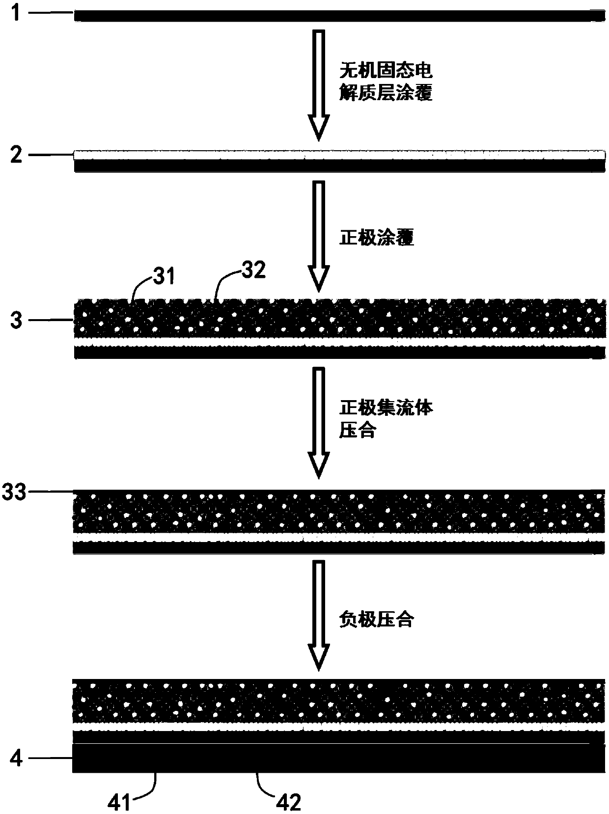
[0039] The solid-state battery of this embodiment, the schematic diagram of the specific preparation process is as follows figure 1 As shown, the following steps are taken:

[0040] 1) Dissolving the polymer electrolyte (polymer matrix and lithium salt) in acetonitrile to prepare a polymer electrolyte slurry, coating the polymer electrolyte slurry on the substrate, and peeling off from the substrate after drying to obtain a polymer electrolyte layer .

[0041] 2) Add the inorganic solid electrolyte and the polymer electrolyte to the solvent acetonitrile to disperse evenly to obtain the inorganic electrolyte layer slurry, coat the inorganic electrolyte layer slurry on one side surface of the polymer electrolyte layer, and dry it on the surface of the polymer electrolyte layer An inorganic electrolyte layer is formed.

[0042] 3) Add positive electrode materials, conductive additives, polymer electrolytes, and inorganic solid electrolytes into dimethylformamide DMF to disperse...

Embodiment 2

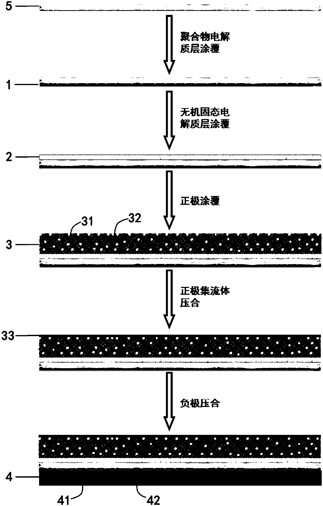
[0049] The solid-state battery of this embodiment, the schematic diagram of the specific preparation process is as follows figure 2 As shown, the following steps are taken:

[0050] 1) Add polymer electrolyte and inorganic solid electrolyte to acetonitrile to disperse evenly, then pour into the porous support framework (or immerse the porous support framework in the pouring slurry for 5 minutes), and form the support framework layer after drying.

[0051] 2) dissolving the polymer electrolyte in acetonitrile to prepare a polymer electrolyte slurry, coating the polymer electrolyte slurry on the surface of the negative electrode side of the supporting skeleton layer, and forming a polymer electrolyte layer after drying;

[0052] Adding inorganic solid electrolyte and polymer electrolyte into acetonitrile and dispersing evenly to obtain inorganic electrolyte layer slurry, coating the inorganic electrolyte layer slurry on the surface of the positive electrode side of the supporti...


PUM

PropertyMeasurementUnit
Thicknessaaaaaaaaaa

Abstract

The invention relates to a solid-state battery and a preparation method thereof. The solid-state battery comprises a positive electrode, a negative electrode and a solid-state electrolyte membrane compounded between the positive electrode and the negative electrode, wherein the positive electrode comprises a positive electrode current collector and a positive electrode material layer coated on thepositive electrode current collector, the positive electrode material layer contains a positive electrode material and a binder, and the binder is a polymer electrolyte; the electrolyte membrane comprises an inorganic electrolyte layer attached to the positive electrode and a polymer electrolyte layer attached to the negative electrode, and the inorganic electrolyte layer contains an inorganic solid-state electrolyte and a polymer electrolyte. According to the solid-state battery provided by the invention, on the basis of using the composite electrolyte membrane, the polymer electrolyte is used as the binder in the positive electrode material layer and the inorganic electrolyte layer, and the polymer electrolyte has lithium ion conductivity, so that the improvement of a conductive networkof the positive electrode material layer is facilitated, and the compatibility of the positive electrode and the inorganic electrolyte membrane is improved, thereby being capable of effectively reducing the internal resistance of the battery, and promoting the improvement of the overall performance of the battery.

Description

technical field [0001] The invention belongs to the field of lithium-ion batteries, and in particular relates to a solid-state battery and a preparation method thereof. Background technique [0002] The development of new energy vehicles is of great significance for alleviating environmental pollution and energy crisis. The power battery as an energy source plays a decisive role in the performance of new energy vehicles. Lithium-ion batteries have become the first choice for new energy vehicle batteries due to their advantages such as high energy density, high power density, long life, and no memory effect. [0003] The rapid development of new energy vehicles has put forward higher requirements for the safety and energy density of power battery systems. Currently, liquid lithium-ion batteries used in mainstream power batteries have certain safety hazards because they contain liquid organic electrolytes, and their The limited pressure window limits the further improvement o...

Claims


Application Information

Patent Timeline
IPC IPC(8): H01M10/0525H01M10/0585H01M10/056H01M4/139H01M4/04H01M4/62
CPCH01M4/0407H01M4/139H01M4/62H01M4/622H01M10/0525H01M10/056H01M10/0585H01M2300/0094Y02E60/10Y02P70/50
Inventor 李云明周时国曹瑞中廖华平张二勇尹利超彭能岭
Owner 郑州宇通集团有限公司
Why Eureka
Try Eureka