
Flue gas denitration equipment

A denitrification and equipment technology, applied in the field of flue gas purification, can solve the problems of flue gas inflow, lower flue gas denitrification efficiency, flue gas denitrification efficiency, etc., and achieve the effect of improving efficiency and facilitating full reaction

Inactive Publication Date: 2019-12-20
黎泽辉
View PDF4 Cites 0 Cited by
  • Summary
  • Abstract
  • Description
  • Claims
  • Application Information

AI Technical Summary

Problems solved by technology

[0003] The working principle of the existing flue gas denitrification is that the flue gas is introduced into the denitrification equipment, and then a certain amount of nitrogen is injected into the equipment to neutralize the nitrate in the flue gas, and then the flue gas passes through the catalyst layer to further remove the flue gas. Harmful substances in the gas, while the flue gas from the filter or garbage incinerator is discharged by the rising strength of the flue gas, coupled with the light weight of the dust particles, the dust particles are entrained and moved by the rising flow rate of the flue gas, and move with the flue gas When the gas enters the denitrification equipment, when the dust moves down, affected by the flow velocity and gravity of the flue gas, part of the dust falls on the catalyst layer, causing the surface layer of the catalyst to be covered by dust, and the internal gap is gradually filled by dust, resulting in the change of the ventilation speed of the catalyst layer, and the smoke As the gas velocity slows down, the contact area between the catalyst layer and the flue gas becomes smaller, resulting in a decrease in the denitrification efficiency of the flue gas and incomplete denitrification. At the same time, the other part continues to move with the flue gas. During the downward movement, the dust and the catalyst layer contact each other, resulting in Physical friction, with the increase of time, causes the wear of the catalyst layer, shortens the reaction time between the catalyst layer and the flue gas, further reduces the efficiency of flue gas denitrification, and the flue gas also contains a large amount of sulfur dioxide and sulfur dioxide in the process of emission. It is also one of the gas sources that pollute the atmosphere. Since the denitrification equipment does not contain sulfur removal equipment, the unpurified flue gas flows into the atmosphere, further affecting the air quality

Method used


Image

  • Flue gas denitration equipment
  • Flue gas denitration equipment
  • Flue gas denitration equipment

Examples


Embodiment Construction

[0021] The following will clearly and completely describe the technical solutions in the embodiments of the present invention with reference to the accompanying drawings in the embodiments of the present invention. Obviously, the described embodiments are only some, not all, embodiments of the present invention. Based on the embodiments of the present invention, all other embodiments obtained by persons of ordinary skill in the art without making creative efforts belong to the protection scope of the present invention.

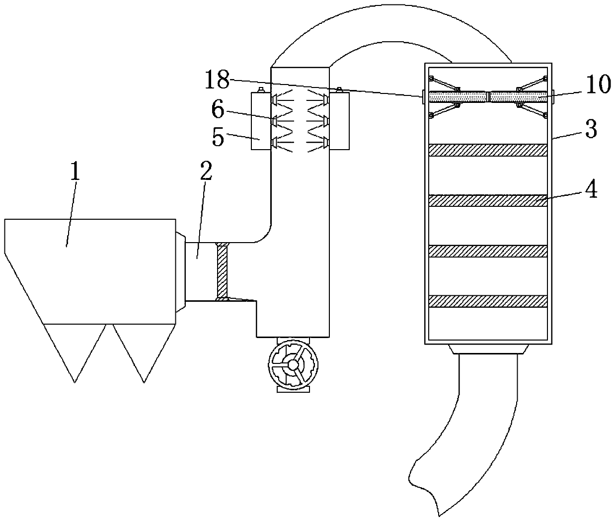
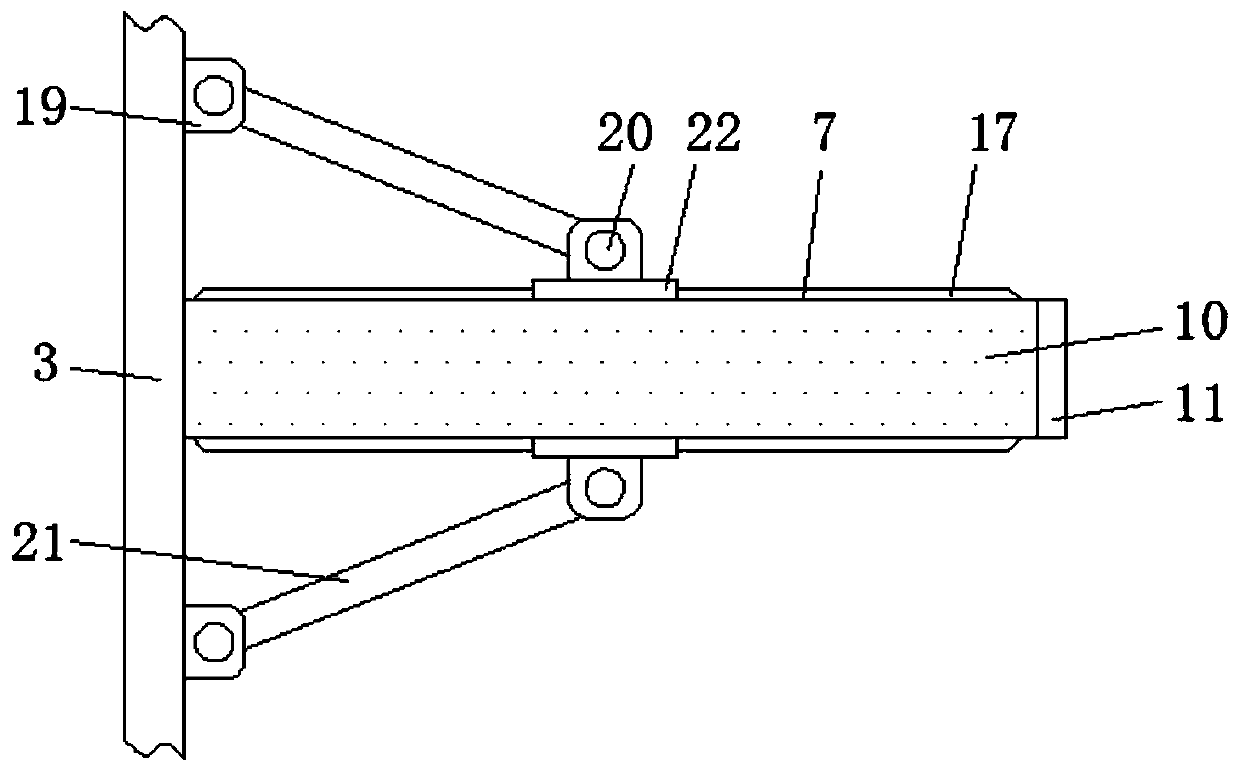
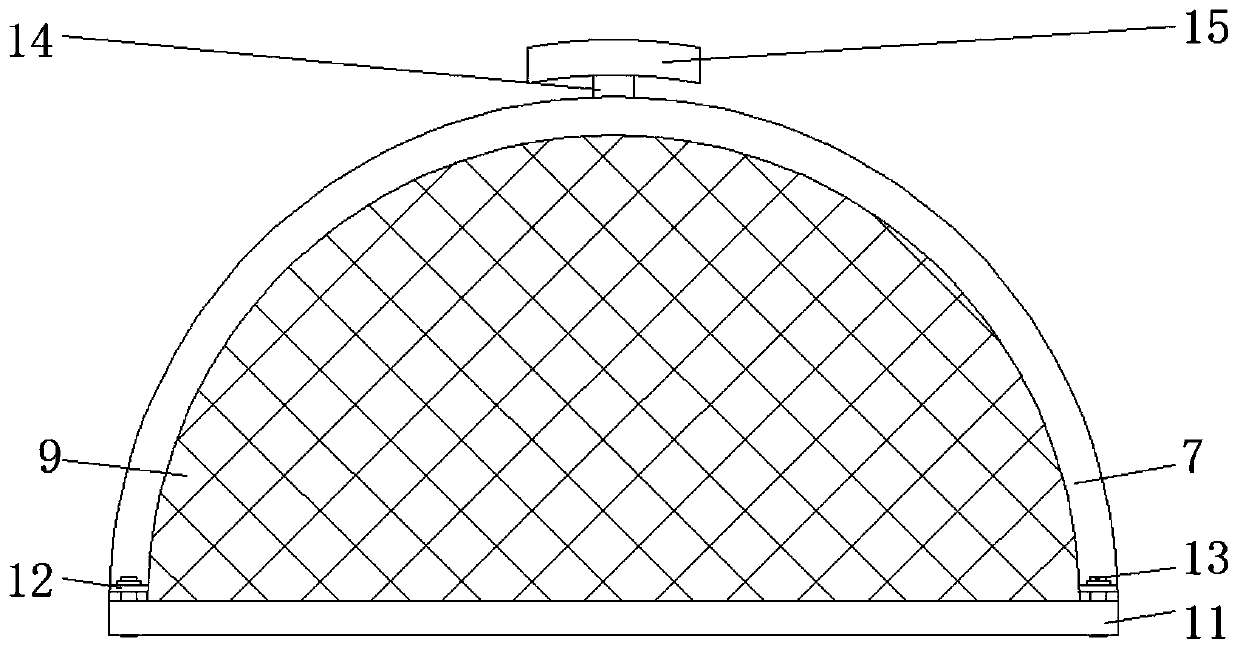
[0022] see Figure 1-6 , a kind of flue gas denitrification equipment, including intake pipe 1, guide pipe 2, denitrification tower 3, catalyst layer 4, guide pipe 2 connected to the side of the intake pipe 1, denitrification tower 3 connected to the end of the guide pipe 2 , the catalyst layer 4 is installed inside the denitrification tower 3, a water tank 5 is installed outside the guide pipe 2, and the side of the water tank 5 communicates with a nozzle 6 l...


PUM


Abstract

The invention relates to the technical field of flue gas purification, and discloses flue gas denitration equipment. The equipment comprises a denitration tower; a water tank is installed outside a guide pipe, and a spray nozzle arranged inside the guide pipe communicates with the side surface of the water tank; and the inner wall of the denitration tower is slidably connected with a filler plate,and the filler plate is filled with fillers. According to the flue gas denitration equipment, part of water mist is entrained in flue gas, and static electricity entrained on particles is removed, sothat the dust removal efficiency is improved; the fillers react with the flue gas, so that the sulfur dioxide and the calcium oxide react to generate an annoying heat phenomenon, and the flue gas isdirectly heated, specifically, the higher the temperature of the flue gas is, the higher the reaction efficiency is, and the more thorough the denitration is; and meanwhile, calcium sulfite and waterare generated, the water automatically flows downwards under the influence of gravity, so that dust on a catalyst layer is removed, the surface of the catalyst layer is always in a clean state, the full reaction between the flue gas and the catalyst layer is facilitated, and the flue gas denitration always keeps a better state.

Description

technical field [0001] The invention relates to the technical field of flue gas purification, in particular to a flue gas denitrification device. Background technique [0002] Flue gas denitrification refers to the reduction of generated NOX to N2, thereby removing NOX in flue gas. According to the treatment process, it can be divided into wet denitrification and dry denitrification. [0003] The working principle of the existing flue gas denitrification is that the flue gas is introduced into the denitrification equipment, and then a certain amount of nitrogen is injected into the equipment to neutralize the nitrate in the flue gas, and then the flue gas passes through the catalyst layer to further remove the flue gas. Harmful substances in the gas, while the flue gas from the filter or garbage incinerator is discharged by the rising strength of the flue gas, coupled with the light weight of the dust particles, the dust particles are entrained and moved by the rising flow r...

Claims


Application Information

Patent Timeline
IPC IPC(8): B01D47/06B01D53/86B01D53/56B01D53/50
CPCB01D47/06B01D53/50B01D53/8631
Inventor 不公告发明人
Owner 黎泽辉
Learn More