Transfer printing and manufacturing method of beam film type piezoelectric array printing head

A piezoelectric array and manufacturing method technology, applied in printing and other directions, can solve the problem of difficult to realize patterned piezoelectric ceramic driving materials, difficult to prepare piezoelectric ceramic materials, and difficult to realize beam-film piezoelectric array printing with wide structural applicability First-class problem, to achieve the effect of strong bonding process compatibility, wide structural applicability, and strong process compatibility

Active Publication Date: 2019-12-20
XI AN JIAOTONG UNIV
View PDF7 Cites 0 Cited by
  • Summary
  • Abstract
  • Description
  • Claims
  • Application Information

AI Technical Summary

Problems solved by technology

[0004] Since the piezoelectric ceramic driving material in the beam-membrane print head is set in the groove structure composed of the separation beam and the vibrating membrane, and the height is lower than the separation beam, methods such as grinding thinning method, screen printing method, sol-gel method, etc. It is difficult to realize the preparation of such a beam-membrane piezoelectric driving structure with patterned piezoelectric ceramic driving material in the groove
In principle, the magnetron sputtering method can realize conformal coverage of piezoelectric ceramic materials to realize the preparation of beam-membrane piezoelectric driving structures, but limited by the process capability itself, it can generally only be used to develop piezoelectric ceramic materials with a thickness of about several microns. Thin-film beam-membrane piezoelectric array print heads are difficult to prepare piezoelectric ceramic materials with higher thickness, and the magnetron sputtering method has high requirements for the aspect ratio of the beam-membrane groove structure. The print head structure has great limitations
Therefore, it is difficult for the existing technology to realize the fabrication of beam-membrane piezoelectric array printheads with wide structural applicability

Method used


Image

  • Transfer printing and manufacturing method of beam film type piezoelectric array printing head
  • Transfer printing and manufacturing method of beam film type piezoelectric array printing head
  • Transfer printing and manufacturing method of beam film type piezoelectric array printing head

Examples


Embodiment Construction

[0025] In order to make the object, technical solution and advantages of the present invention more clear, the present invention will be further described in detail below in conjunction with the accompanying drawings and embodiments. It should be understood that the specific embodiments described here are only used to explain the present invention, not to limit the present invention.

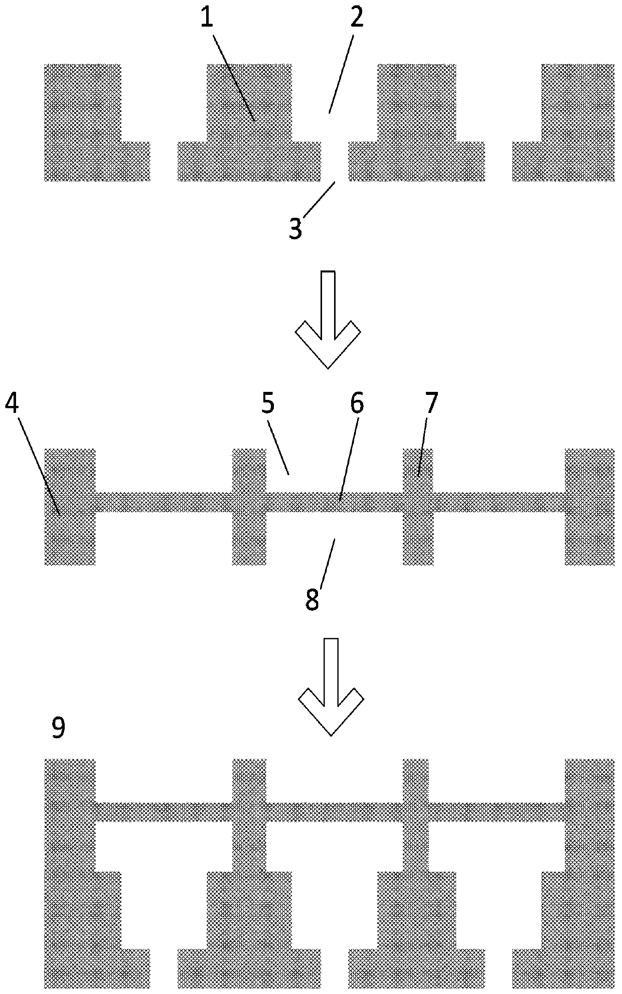
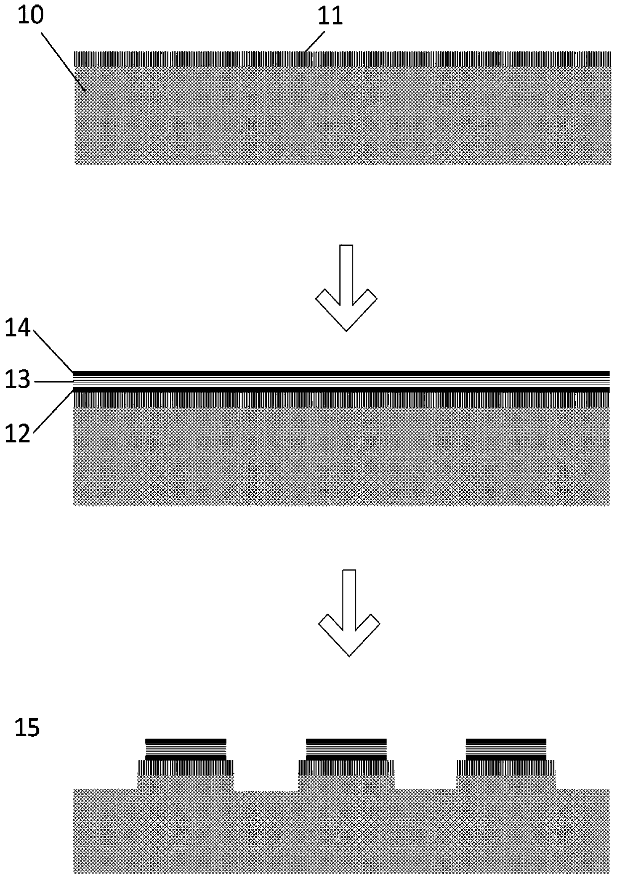
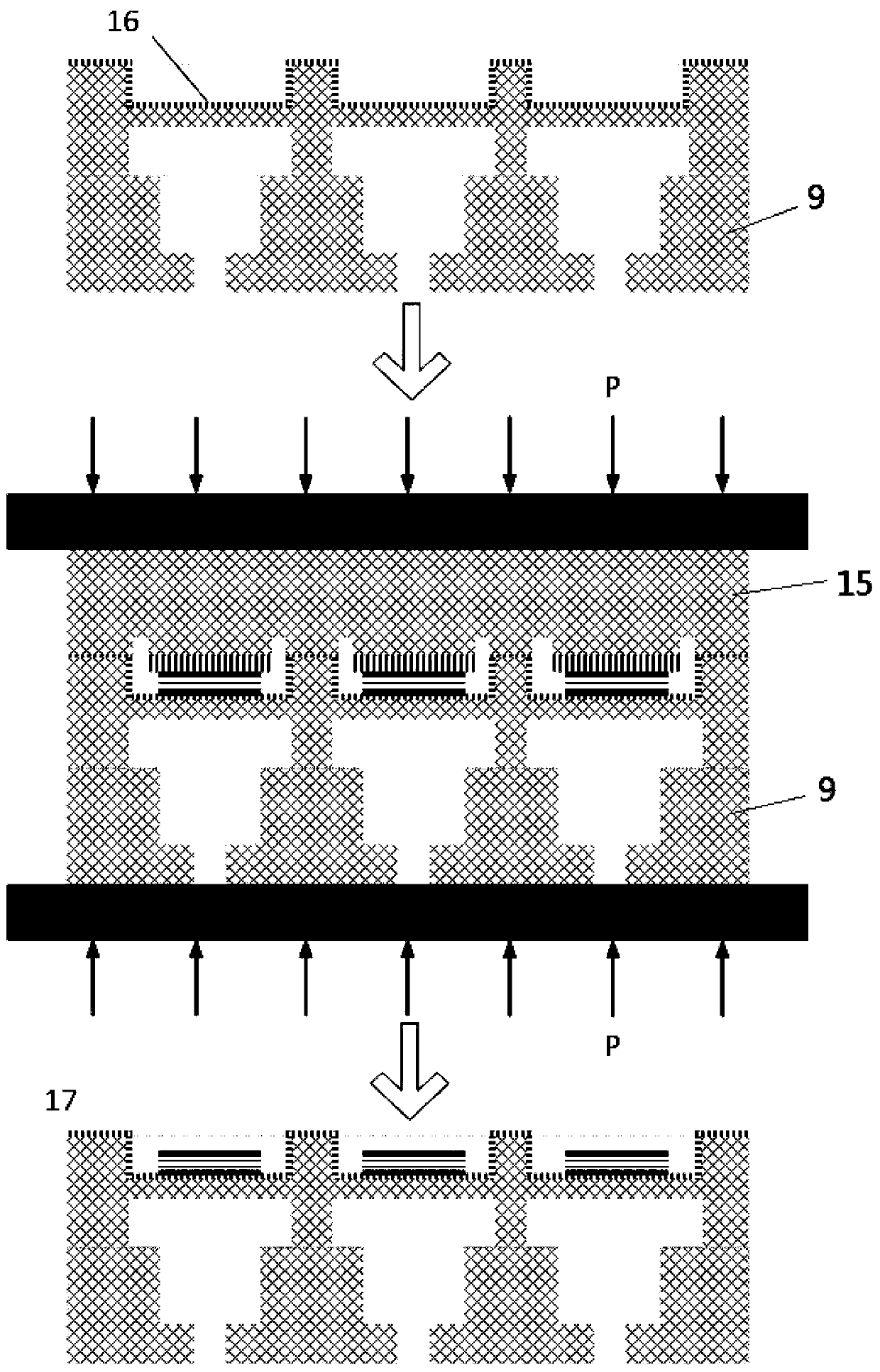
[0026] A transfer printing manufacturing method of a beam-membrane piezoelectric array print head. Firstly, a liquid channel plate of a beam-membrane piezoelectric array print head is prepared, and a piezoelectric drive plate of a beam-membrane piezoelectric array print head is separately prepared, and then passed The transfer printing method combines the piezoelectric driving structure on the piezoelectric drive plate of the beam-membrane piezoelectric array print head with the liquid channel plate of the beam-membrane piezoelectric array print head to form a complete beam-membrane piezoelectric...


PUM


Abstract

A transfer printing and manufacturing method of a beam film type piezoelectric array printing head includes the steps of preparing a beam film type piezoelectric array printing head liquid channel plate, meanwhile independently preparing a beam film type piezoelectric array printing head piezoelectric driving plate, and combining a piezoelectric driving structure on the beam film type piezoelectric array printing head piezoelectric driving plate with the beam film type piezoelectric array printing head liquid channel plate through a transfer printing mode to form the complete beam film type piezoelectric array printing head. The method is high in technological compatibility and low in cost, and the beam film type piezoelectric array printing head with wide structure applicability is manufactured.

Description

technical field [0001] The invention belongs to the technical field of droplet jetting printing, and in particular relates to a transfer printing manufacturing method of a beam-membrane piezoelectric array printing head. Background technique [0002] The beam-membrane piezoelectric array print head reduces the mechanical crosstalk between the vibrating membranes and isolates the electrical crosstalk between the electrodes through the separation beams arranged between adjacent piezoelectric jetting units, which helps to improve the piezoelectric array printing. The array density and ejection frequency of the head ejection unit have great application prospects in the field of droplet jet printing head and droplet jet printing. [0003] In the process of manufacturing beam-membrane piezoelectric array printheads, it is particularly important to prepare patterned piezoelectric ceramic driving materials in the groove structure composed of separating beams and vibrating membranes....

Claims


Application Information

Patent Timeline
Patent Type & Authority Applications(China)
IPC IPC(8): B41J2/16
CPCB41J2/1607B41J2/1621
Inventor 邵金友杨正杰王小培王春慧田洪淼平鹏祥严超
Owner XI AN JIAOTONG UNIV
Why Eureka
Try Eureka