Primary side regulation control system and primary side regulation control method of active clamp flyback converter
A technology of flyback converter and primary side regulation, which is applied in the direction of control/regulation system, regulation of electric variables, conversion of DC power input to DC power output, etc. Successful development, non-linear changes in working waveforms, etc.
- Summary
- Abstract
- Description
- Claims
- Application Information
AI Technical Summary
Problems solved by technology
Method used
Image
Examples
Embodiment 1
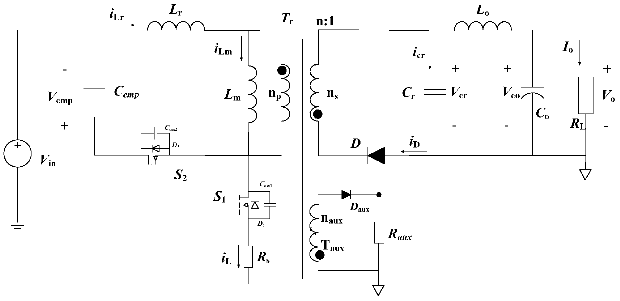
[0062] Example 1. In this preferred embodiment, a secondary-side resonant active-clamp flyback converter with primary-side auxiliary winding is used, and the topological structure diagram of the converter is as follows figure 1 shown. The active clamp flyback converter consists of an input DC source V in , Transformer T r , resonant inductance L r , magnetizing inductance L m , main power tube S 1 , clamp tube S 2 , the clamp capacitor C cmp , the inductor current sense resistor R s , secondary rectifier diode D, resonant capacitor C r , the output filter capacitor C o , the output filter inductance L o , load impedance R L , auxiliary winding diode D aux , the auxiliary winding resistor R aux . where the resonant inductance L r , Exciting inductance L m , primary side auxiliary winding T aux can be regarded as a transformer T r a part of.
[0063] Resonant inductance L r Connect one end of the input DC source V in of the positive terminal, the resonant in...
Embodiment 2
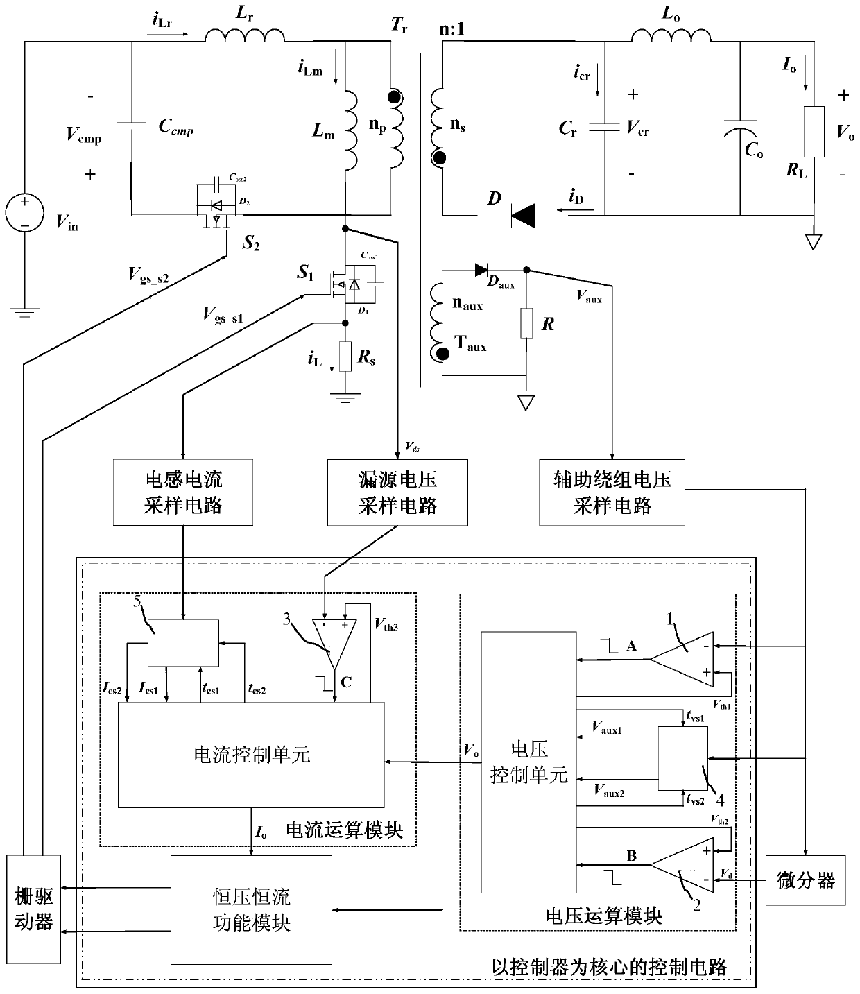
[0065] Example 2. The structure of the primary regulation control system of the active clamp flyback converter proposed by the present invention is as follows: figure 2 shown. The control system includes an inductor current sampling circuit, a drain-source voltage sampling circuit, an auxiliary winding voltage sampling circuit, a gate driver, a control circuit with a controller as the core, and a differentiator. Among them, the control circuit with the controller as the core includes a voltage operation module, a current operation module, and a constant voltage and constant current function module.
[0066] The voltage operation module includes: a first comparator 1, a second comparator 2, a first analog-to-digital converter 4, and a voltage control unit; the inverting input terminal of the first comparator 1 receives the auxiliary winding voltage output by the auxiliary winding voltage sampling circuit , the inverting input terminal of the second comparator 2 receives the ...
Embodiment 3
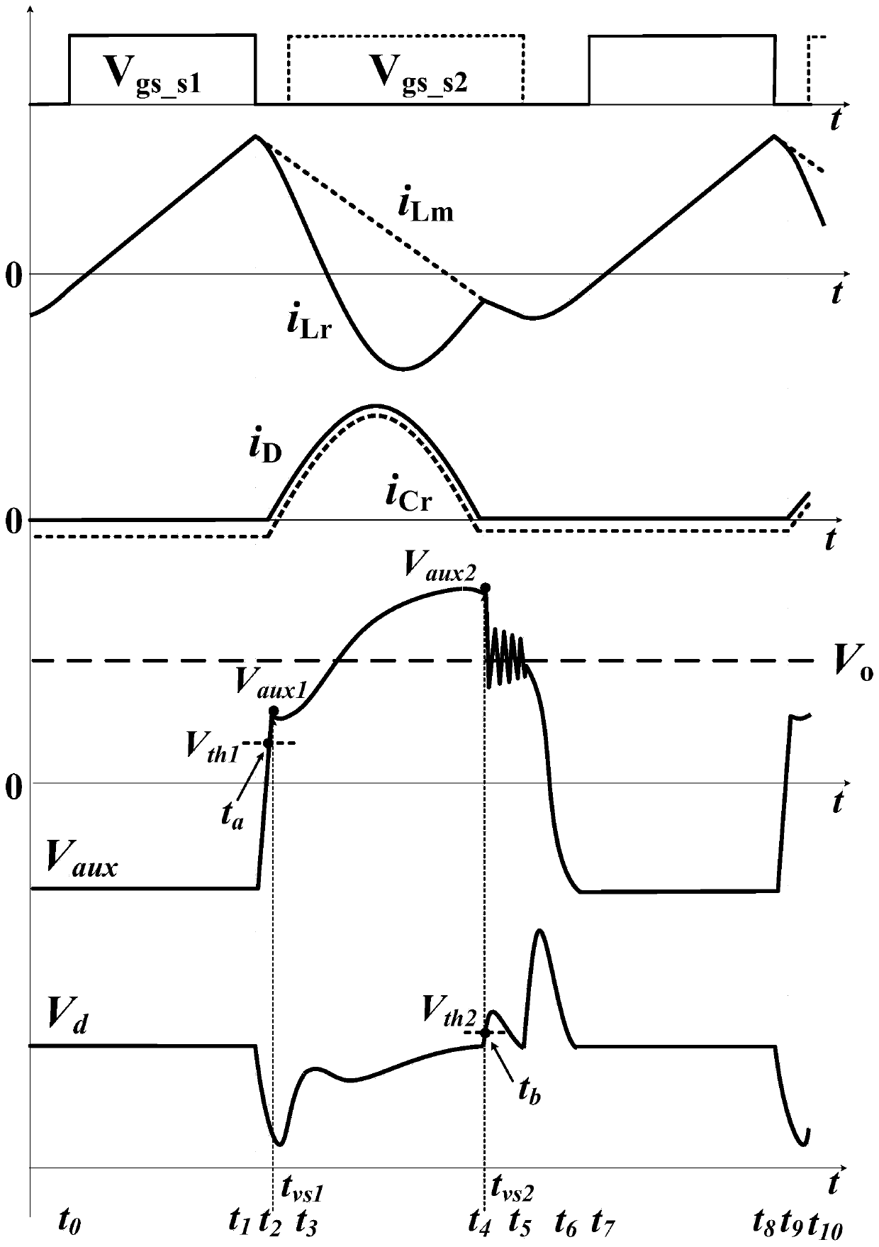
[0078] Example 3. The primary side adjustment control method of the active clamp flyback converter proposed by the invention can realize the active clamp flyback converter working in a constant voltage control mode. When the constant voltage control mode is realized, only the voltage operation module is used to collect the auxiliary winding voltage and predict the output voltage. In this preferred embodiment, the primary regulation control method of the active clamp flyback converter samples the voltage, and the related waveforms are as follows image 3 shown.
[0079] image 3 Among them, from top to bottom are: main power tube S 1 The gate-to-source terminal voltage V gs_S1 and clamp tube S 2 The gate-to-source terminal voltage V gs_S2 Time-varying waveform, resonant inductor current i Lr and the magnetizing inductor current i Lm Time-varying waveform, secondary rectifier diode current i D and the resonant capacitor current i Cr time-varying waveform, the auxiliary...
PUM
 Abstract
Description
Claims
Application Information
 - R&D
- Intellectual Property
- Life Sciences
- Materials
- Tech Scout
- Unparalleled Data Quality
- Higher Quality Content
- 60% Fewer Hallucinations
Browse by: Latest US Patents, China's latest patents, Technical Efficacy Thesaurus, Application Domain, Technology Topic, Popular Technical Reports.
© 2025 PatSnap. All rights reserved.Legal|Privacy policy|Modern Slavery Act Transparency Statement|Sitemap|About US| Contact US: help@patsnap.com


