Cylindrical lens focusing-based handheld welding optical mechanism and working method thereof

A technology of cylindrical lens and optical mechanism, applied in welding equipment, laser welding equipment, manufacturing tools, etc., can solve the problems of heavy hand-held welding head, unfavorable energy utilization welding speed, unfriendly customer experience, etc. The structural design is less difficult, the laser welding defects are reduced, and the structural design is novel.

Inactive Publication Date: 2019-12-27
SHANGHAI EMPOWER AUTOMATION TECH CO LTD
View PDF0 Cites 1 Cited by
  • Summary
  • Abstract
  • Description
  • Claims
  • Application Information

AI Technical Summary

Problems solved by technology

[0005] At present, there are two kinds of handheld welding optical solutions, one is fixed spot welding, that is, the main body is conventional collimation and focusing, and an additional mirror is added to change the beam transmission direction or other auxiliary methods to meet the ergonomic application of handheld welding. Make sure that the hand-held welding processing head is small enough to reduce cost and weight, so that it is easier to hold it for a long time. The disadvantage is that the lap joints of different plates are wide, and out-of-focus welding is required. The energy density will be greatly reduced, which is not conducive to energy utilization and welding speed. promote
[0006] The other is scanning spot welding, that is, the change of different patterns of the focused spot is realized by means such as oscillating mirror scanning, wedge mirror rotating scanning, etc. The most direct is to realize linear or approximate linear scanning perpendicular to the weld seam direction to increase welding. Seam width adaptability, this solution needs to increase the motor and the corresponding control system, on the one hand, it will greatly increase the cost, on the other hand, it will cause the weight of the hand-held welding processing head to be heavy, which is very unfriendly to the customer experience

Method used


Image

  • Cylindrical lens focusing-based handheld welding optical mechanism and working method thereof

Examples


Embodiment Construction

[0028] The following will clearly and completely describe the technical solutions in the embodiments of the present invention with reference to the accompanying drawings in the embodiments of the present invention. Obviously, the described embodiments are only some, not all, embodiments of the present invention. Based on the embodiments of the present invention, all other embodiments obtained by persons of ordinary skill in the art without making creative efforts belong to the protection scope of the present invention.

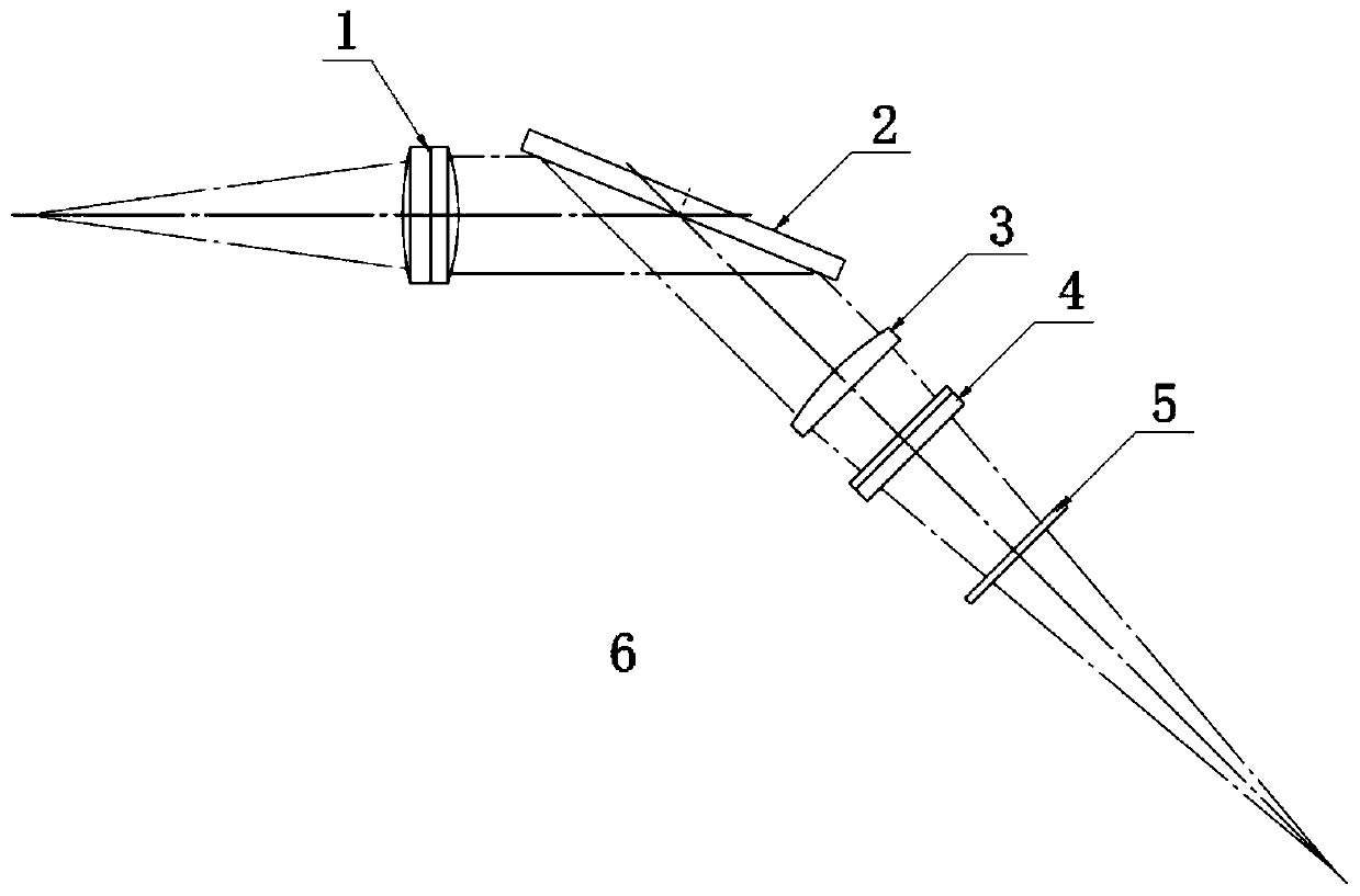
[0029] see figure 1 , the present invention provides a technical solution: a handheld welding optical mechanism based on cylindrical lens focusing, including a handheld welding optical mechanism 6, a collimating lens group 1, a plane mirror 2, a first cylindrical lens 3, a second column A surface lens 4, a protective mirror 5, a collimator lens group 1, a flat mirror 2, a first cylindrical lens 3, a second cylindrical lens 4, and a protective mirror 5 are arra...


PUM

PropertyMeasurementUnit
angle of incidenceaaaaaaaaaa

Abstract

The invention discloses a cylindrical lens focusing-based handheld welding optical mechanism and a working method thereof. The mechanism comprises a handheld welding optical mechanism body, a collimating mirror set, a planar mirror, a first cylindrical lens, a second cylindrical lens and a protective glass. The mechanism has the advantages that the structural design is novel, the one-piece cylindrical lens is moved in the optical axis direction based on the one-way focusing characteristic of the cylindrical lenses, the elliptic shaping of focused beam segment spots and the continuous adjustable length in one-way direction of the any-section spots are realized, the laser power density of the focusing spots is conveniently reduced, so that the power required by plate welding is reduced, thewelding speed is conveniently improved, the adaptability of the welding seam width is conveniently improved, and the mechanism is suitable for laser welding applications, and is particularly suitablefor handheld welding applications of different seam-width plates.

Description

technical field [0001] The invention relates to the technical field of laser welding, in particular to a focusing handheld welding optical mechanism based on a cylindrical lens and a working method thereof. Background technique [0002] Laser processing technology covers various laser processing technologies such as laser cutting, welding, quenching, drilling, micromachining, etc., and utilizes the basic characteristics of the interaction between laser and matter. Because the laser beam has the advantages of non-contact with the processing material, fast processing speed and excellent quality, it has established that the laser processing technology is an irreplaceable high-tech. [0003] Due to the advantages of high electro-optical conversion efficiency, good fiber flexibility, high coupling efficiency, and good beam quality, as well as the emergence of high-power lasers, fiber lasers have made their market share increasingly prominent. At present, fiber-coupled output lase...

Claims


Application Information

Patent Timeline
Patent Type & Authority Applications(China)
IPC IPC(8): B23K26/064
CPCB23K26/064B23K26/0643B23K26/0648
Inventor 邵华江李思佳
Owner SHANGHAI EMPOWER AUTOMATION TECH CO LTD
Why Eureka
Try Eureka