
Support cast-in-place, pier top rotation and cast in cantilever combined construction method for continuous beams

A construction method and technology of cast-in-place piers, which are applied in bridges, buildings, bridge construction, etc., can solve the problems of complex internal force state, heavy weight, and technical difficulty, etc., achieve good environmental protection and energy saving benefits, ensure the laying period, reduce The effect of huge investments

Inactive Publication Date: 2019-12-31
CHINA RAILWAY NO 3 GRP CO LTD +1
View PDF9 Cites 3 Cited by
  • Summary
  • Abstract
  • Description
  • Claims
  • Application Information

AI Technical Summary

Problems solved by technology

[0004] However, when the continuous beam integrates the three construction techniques of hanging basket cantilever casting, cast-in-place support, and horizontal rotation of the pier top, there are many procedures, the internal force state of the structure is complicated during the construction stage, and the cumulative errors of materials, structural dimensions, and construction operation errors are relatively large. Large, linear control is difficult
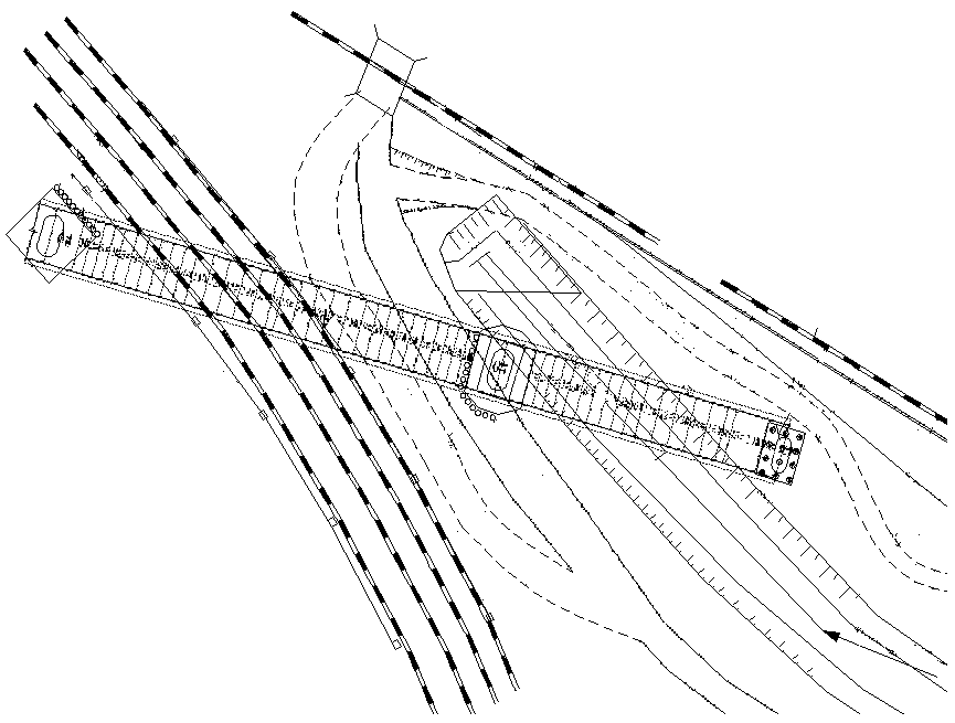
Half of the continuous beam is constructed by bracket cast-in-place + pier top swivel method, and the other half is constructed by hanging basket cantilever pouring method, especially when the weight of the pier top swivel is heavy and the swivel length is long, the technical difficulty is great, and the construction control requires high precision. It is very difficult to control the balance and posture of the pier top rotation. At the same time, if the bridge is located on the main passageway of the laying structure, the construction period pressure will be high, and it will cross multiple adjacent business lines, which will pose a great safety risk.

Method used


Image

  • Support cast-in-place, pier top rotation and cast in cantilever combined construction method for continuous beams
  • Support cast-in-place, pier top rotation and cast in cantilever combined construction method for continuous beams
  • Support cast-in-place, pier top rotation and cast in cantilever combined construction method for continuous beams

Examples


Embodiment Construction

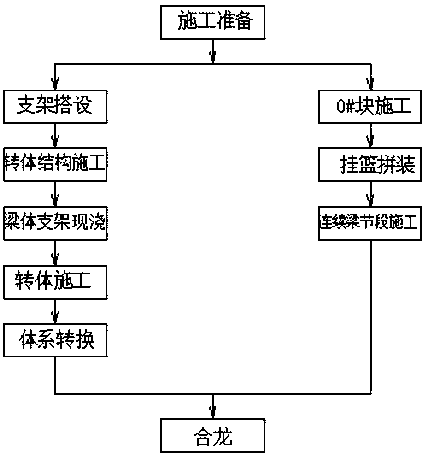
[0048] Such as figure 1 As shown, a continuous beam support cast-in-situ pier top rotation and cantilever pouring combined construction method includes the following methods, 1# pier construction and 2# pier construction respectively, wherein the construction steps of 1# pier are as follows.

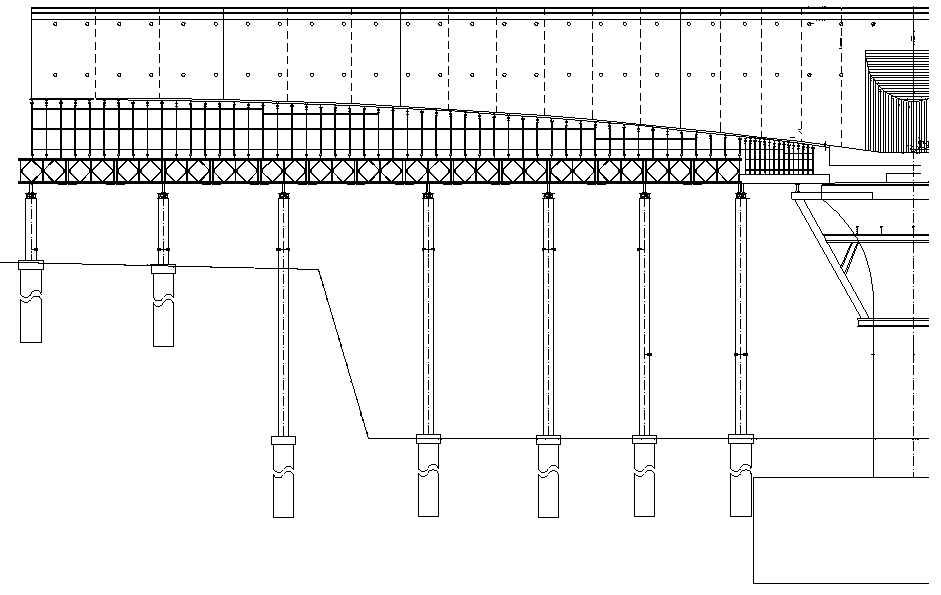
[0049] S100~Strut erection construction: after the erection of the support is completed and the acceptance of the support is confirmed, carry out preloading to eliminate the non-elastic deformation of the support, determine the elastic deformation value, and then determine the elevation of the vertical formwork.

[0050] S200~Pier top swivel structure installation and construction.

[0051] The pier top swivel structure consists of an upper turntable, a lower turntable, a spherical joint, and a swivel traction system.

[0052] (1) Lower turntable:

[0053] The lower turntable plays the role of supporting the whole weight of the structure. The lower turntable is made of C50 concrete. ...


PUM


Abstract

The invention belongs to the technical field of bridge construction, and particularly relates to a support cast-in-place, pier top rotation and cast in cantilever combined construction method for continuous beams. The support cast-in-place, pier top rotation and cast in cantilever combined construction method for the continuous beams comprises the following steps of 1# pier construction and 2# pier construction. The 1# pier construction comprises the following steps that: S100: support building construction: after the support finishes being built and the support confirms to be qualified in acceptance, carrying out piling preloading, eliminating the non-elastic deformation of the support, and determining an elastic deformation value so as to determine formwork erection elevation; S200: theinstallation construction of a pier top rotation construction; S300: beam body support cast-in-place construction; S400: the rotation construction of the pier top rotation construction; and S500: system transformation. The 2# pier construction comprises the following steps that: U100: 0#block construction; U200: hanging basket splitting; and U300: continuous beam segment construction: when both the 1# pier and the 2# pier finish being constructed, carrying out closure construction of the continuous beam. The method is short in construction time, a construction site is provided with a regulation space, and meanwhile, an existing railway can prevent from being blocked.

Description

technical field [0001] The invention belongs to the technical field of bridge construction, in particular to a combined construction method of cast-in-place pier top rotation and cantilever pouring of continuous beam supports. Background technique [0002] Continuous beam is an ancient structural system, which has the advantages of small deformation, good structural rigidity, smooth and comfortable driving, less expansion joints, simple maintenance, and strong earthquake resistance. For prestressed concrete continuous beams, the internal force and alignment of the main beam will change continuously with the progress of construction. Before the construction officially starts, although the ideal elevation and internal force value of each construction stage can be obtained through theoretical analysis, the interference of various factors in the actual construction may cause the alignment and internal force state of the completed bridge to deviate from the design requirements, a...

Claims


Application Information

Patent Timeline
Patent Type & Authority Applications(China)
IPC IPC(8): E01D21/00
CPCE01D21/00
Inventor 安延伟王永彬刘志如刘承宏马良陈阳阳郭大林张广乐张金鸽孔德文程佳兴陈永陈宇博李宁
Owner CHINA RAILWAY NO 3 GRP CO LTD
Learn More