Subgrade drainage structure and system and construction method
A drainage structure and drainage system technology, which is applied in the direction of infrastructure engineering, roads, roads, etc., can solve the problems that the roadbed performance cannot meet the demand, reduce the service life of the roadbed and pavement structure, the bearing capacity of the roadbed and the decline of deformation resistance, etc., to achieve Avoid slope soil loss, improve service performance and life, and improve the effect of absorption
- Summary
- Abstract
- Description
- Claims
- Application Information
AI Technical Summary
Problems solved by technology
Method used
Image
Examples
Embodiment 1
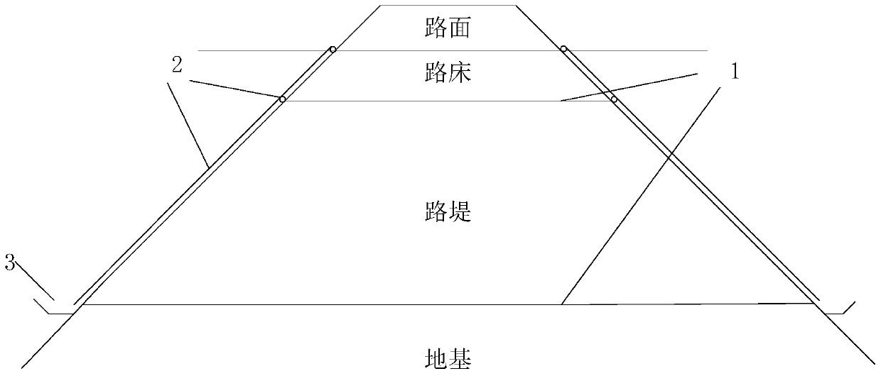
[0049] In a typical implementation of the present application, such as Figure 1-Figure 2 As shown, a subgrade drainage structure using hollow geomembrane is proposed.
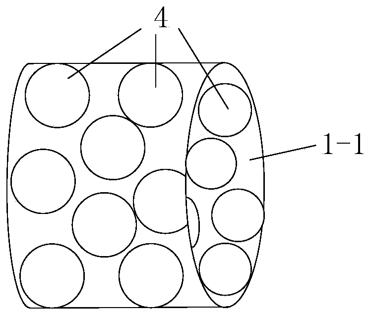
[0050] combine figure 1 As shown, the drainage structure includes an absorption film 1 and a drainage pipe 2 composed of a hollow pipe 1-1, both ends of the hollow pipe are connected to the drainage pipe, and the wall of the hollow pipe is provided with dense micron-sized The opening of the hole diameter, so that after being buried in the roadbed, the micron-sized openings reduce the diameter of the capillary formed in the roadbed, thereby obtaining a capillary with a smaller diameter and increasing the suction of the capillary. The water in the soil around the membrane is sucked into the hollow tube, and the absorbed water is discharged out of the roadbed through the drainage pipes at both ends, which reduces the moisture content in the roadbed soil and improves the humidity inside the roadbed to maintain a ...
Embodiment 2
[0059] In a typical embodiment of the present application, a construction method utilizing the roadbed drainage structure of Embodiment 1 is provided, comprising the following steps:
[0060] Reinforce the foundation part of the subgrade drainage structure to be paved and level the surface;
[0061] Lay the above-mentioned absorbing film on the top of the foundation along the direction of the road extension, and check whether the moisture in the absorbing film can be successfully discharged from both ends of the hollow pipe;
[0062] After successfully paving the bottom absorbing membrane, continue to lay the soil layer by layer according to the roadbed parameters, and arrange the roadbed drainage structure between adjacent layers until it reaches the surface of the roadbed.
[0063] Further, when arranging the roadbed, a drainage ditch is arranged at the interface between the roadbed and the foundation, and after laying the absorbent film, it is checked whether the moisture i...
Embodiment 3
[0068] In another typical embodiment of the present application, a roadbed drainage system including the roadbed drainage structure described in Embodiment 1 is provided.
[0069] At present, the electroosmotic drainage method has been widely used in soft soil consolidation, sludge dewatering, and contaminated soil restoration. The electroosmotic drainage method is mostly used in saturated soils. However, due to the climate and soil quality of our country, most of the highway subgrades are unsaturated soil subgrades. Therefore, this application is aimed at the above problems. The method is applied to the unsaturated soil subgrade, which plays a role in reducing the moisture content and increasing the bearing capacity.
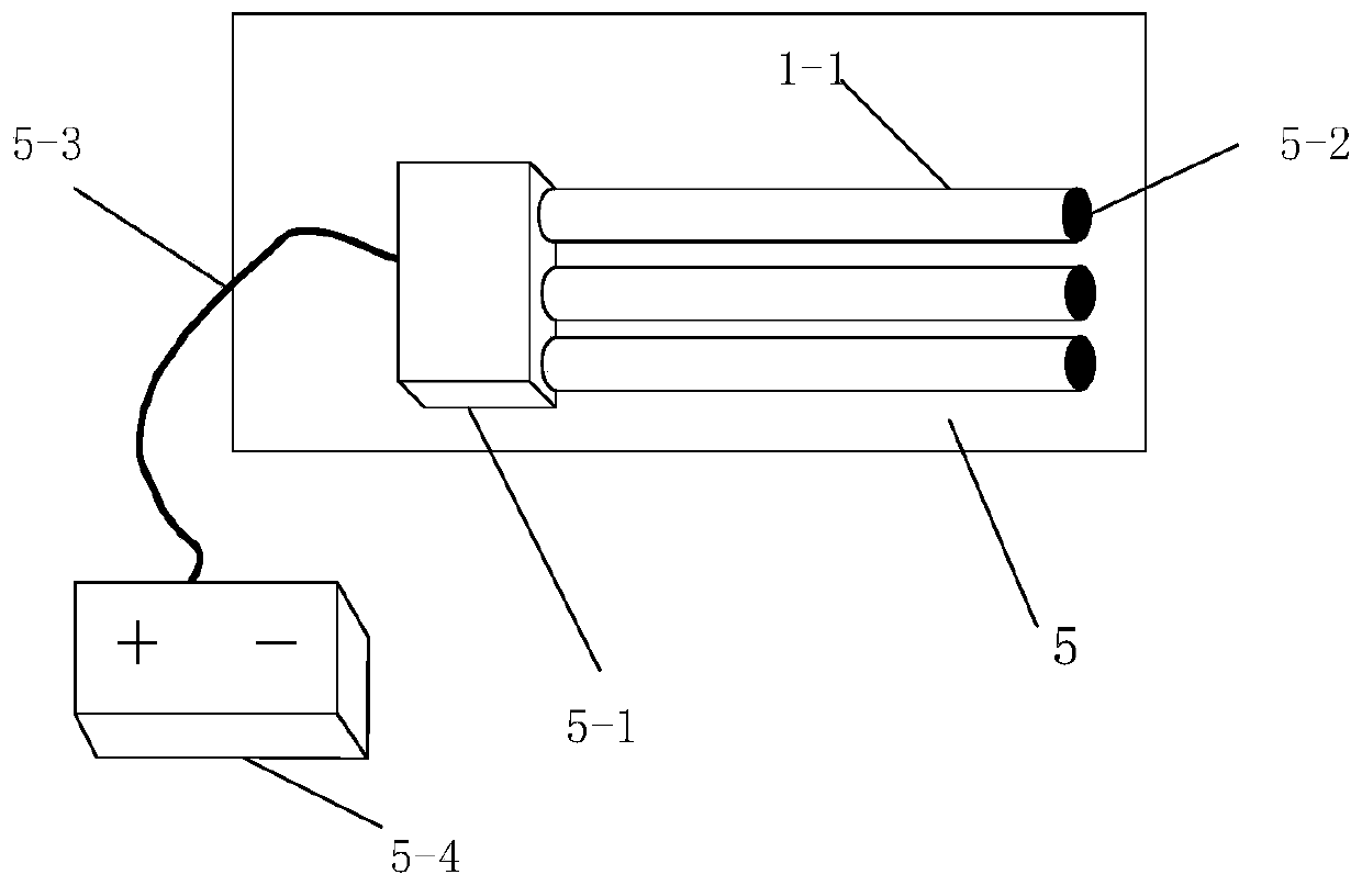
[0070] Specifically, it includes a roadbed drainage structure, a power supply 5-4, and an electrode structure 5. The electrode structure includes a positive electrode structure 6 and a negative electrode structure 7. The positive electrode structure and the neg...
PUM
| Property | Measurement | Unit |
|---|---|---|
| Aperture | aaaaa | aaaaa |
| Thickness | aaaaa | aaaaa |
Abstract
Description
Claims
Application Information
 - R&D
- Intellectual Property
- Life Sciences
- Materials
- Tech Scout
- Unparalleled Data Quality
- Higher Quality Content
- 60% Fewer Hallucinations
Browse by: Latest US Patents, China's latest patents, Technical Efficacy Thesaurus, Application Domain, Technology Topic, Popular Technical Reports.
© 2025 PatSnap. All rights reserved.Legal|Privacy policy|Modern Slavery Act Transparency Statement|Sitemap|About US| Contact US: help@patsnap.com


