Supercritical hydrothermal combustion device suitable for high-viscosity fuel

A supercritical water and combustion device technology, applied in lighting and heating equipment, mining fluids, boreholes/well components, etc., can solve problems such as high energy consumption and large pollution, achieve high heat energy utilization, save energy, prevent The effect of high temperature burning or even explosion

Pending Publication Date: 2020-01-03
XI AN JIAOTONG UNIV
View PDF0 Cites 12 Cited by
  • Summary
  • Abstract
  • Description
  • Claims
  • Application Information

AI Technical Summary

Problems solved by technology

[0005] In order to overcome the above-mentioned shortcomings of the prior art, the purpose of the present invention is to provide an active cooling supercritical hydrothermal combustion device suitable for high-viscosity fuels, aiming at solving the problem of energy consumption of gas-injection boilers in the steam injection process of heavy oil thermal recovery. In order to solve the problems of high energy consumption and high pollution, by combining the multi-component thermal fluid oil recovery technology with the supercritical hydrothermal combustion technology, the multi-component thermal fluid mainly composed of steam can be directly and efficiently generated in the formation, avoiding the waste in the process of steam transportation. Heat loss, providing a practical heavy oil thermal recovery equipment for deep wells, ultra-deep wells and offshore heavy oil production

Method used


Image

  • Supercritical hydrothermal combustion device suitable for high-viscosity fuel
  • Supercritical hydrothermal combustion device suitable for high-viscosity fuel
  • Supercritical hydrothermal combustion device suitable for high-viscosity fuel

Examples


Embodiment Construction

[0028] The implementation of the present invention will be described in detail below in conjunction with the drawings and examples.

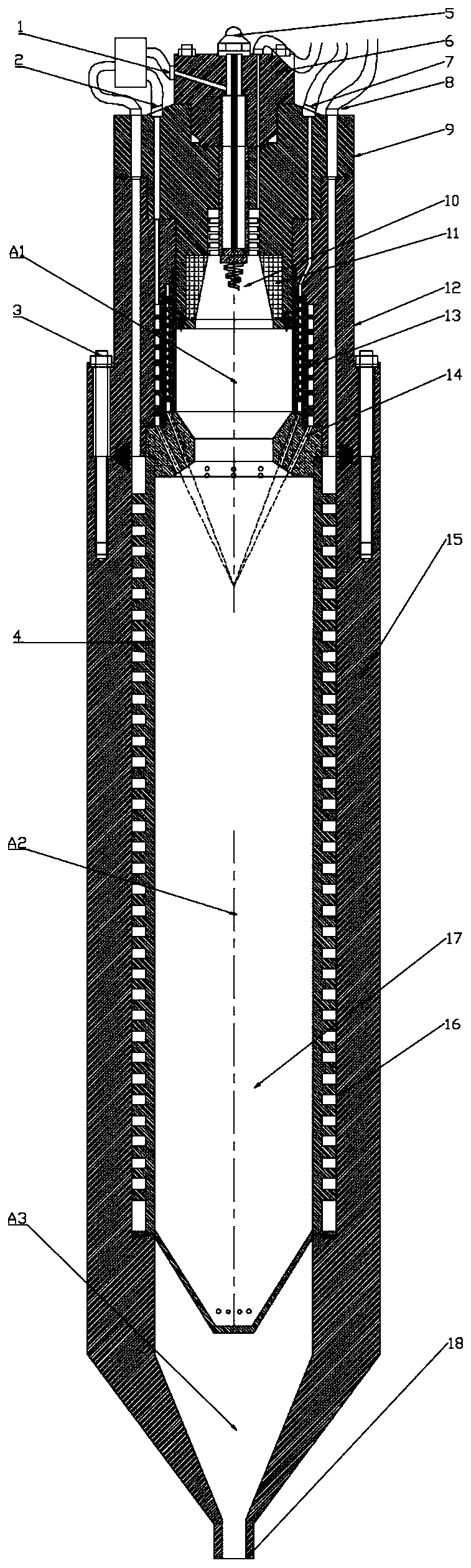
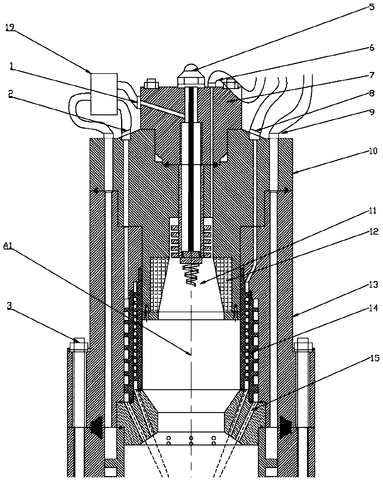
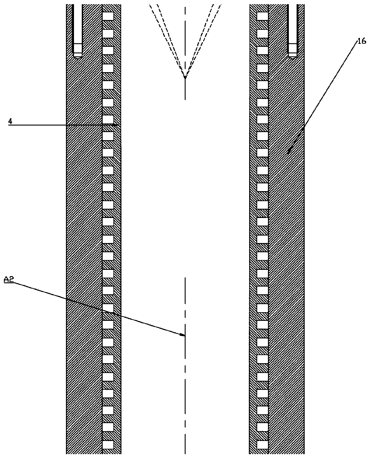
[0029] Such as figure 1 , figure 2 , image 3 and Figure 4 As shown, the present invention is a supercritical hydrothermal combustion device suitable for high-viscosity fuel, which can use crude oil, diesel oil, gasoline, coal slurry or ethanol as fuel, and the device is mainly composed of four main components connected and assembled by bolt groups 3 in sequence : upper end cover 7, middle end cover 10, stable combustion chamber main body one 13 and combustion chamber main body two 16.

[0030] Among them, the upper end cover 7 is provided with a primary fuel inlet 1, a high-energy heating rod 5, and a primary oxidant inlet 6, and the middle end cover 10 is provided with a secondary fuel inlet 2, a secondary oxidant inlet 8, and a reactant primary nozzle 11, And can further set up the cold fuel inlet 9, the reactant primary nozzle 11 is co...


PUM


Abstract

The invention provides a supercritical hydrothermal combustion device suitable for high-viscosity fuel. The supercritical hydrothermal combustion device suitable for the high-viscosity fuel is mainlycomposed of an upper end cover, a middle end cover, a first combustion stabilization chamber body and a second combustion chamber body which are sequentially connected and assembled. The upper end cover is provided with a first-grade fuel inlet, a high-energy heating rod and a first-grade oxidizing agent inlet. The middle end cover is provided with a second-grade fuel inlet, a second-grade oxidizing agent inlet and a reactant first-grade spray nozzle. The reactant first-grade spray nozzle communicates with the first-grade fuel inlet. The inner wall of the first combustion stabilization chamberbody is a double-layer-spiral wall, the bottom end of the first combustion stabilization chamber body is provided with a second-grade spray nozzle communicating with the second-grade fuel inlet and the second-grade oxidizing agent inlet. The inner wall of the second combustion chamber main body is a double-spiral cooling wall, and the bottom end of the second combustion chamber main body is provided with an outlet hole group. Finally, a combustion stabilization chamber is formed between the first-grade spray nozzle and the second-grade spray nozzle. A combustion chamber is formed between thesecond-grade spray nozzle and the outlet hole group. A mixing chamber is formed between the outlet hole group and a bottom outlet of a reactor. The supercritical hydrothermal combustion device suitable for the high-viscosity fuel directly generates steam in an oil layer, so that the problems of high energy consumption and heavy pollution caused in the steam injection process of a heavy oil thermalrecovery ground boiler are solved.

Description

technical field [0001] The invention belongs to the technical field of heavy oil exploitation, and in particular relates to a supercritical hydrothermal combustion device suitable for high-viscosity fuel. Background technique [0002] For heavy oil thermal recovery technology, at present, steam injection boilers on the ground are mainly used in oil fields to generate steam, and the steam is injected downhole for steam huff and puff, steam flooding or steam assisted gravity drainage (SAGD). However, the above methods have the following main problems: (1) large heat loss. The smoke exhaust loss of the surface steam generator is about 20%, the heat loss of the surface gas pipeline is about 15%, the heat loss of the injection wellbore is about 10% per kilometer, and the overall thermal efficiency is low; (2) The reservoir depth is limited. In addition to the application depth of steam huff and puff up to 1800 meters, steam flooding and SAGD technology with high recovery rate ar...

Claims


Application Information

Patent Timeline
Patent Type & Authority Applications(China)
IPC IPC(8): F22B3/08E21B43/243
CPCE21B43/243F22B3/08
Inventor 王树众崔成超李艳辉蒋卓航徐海涛任萌萌
Owner XI AN JIAOTONG UNIV
Why Eureka
Try Eureka