Micro-fluidic chip, protein detecting method, protein detecting device and protein detecting system
A microfluidic chip and protein detection technology, applied in the field of protein detection, can solve the problems of poor consistency and repeatability of trace protein detection, unstable immune reaction process, inconvenient and effective control, etc. The effect of unstable reaction and short reaction time
- Summary
- Abstract
- Description
- Claims
- Application Information
AI Technical Summary
Problems solved by technology
Method used
Image
Examples
Embodiment 1
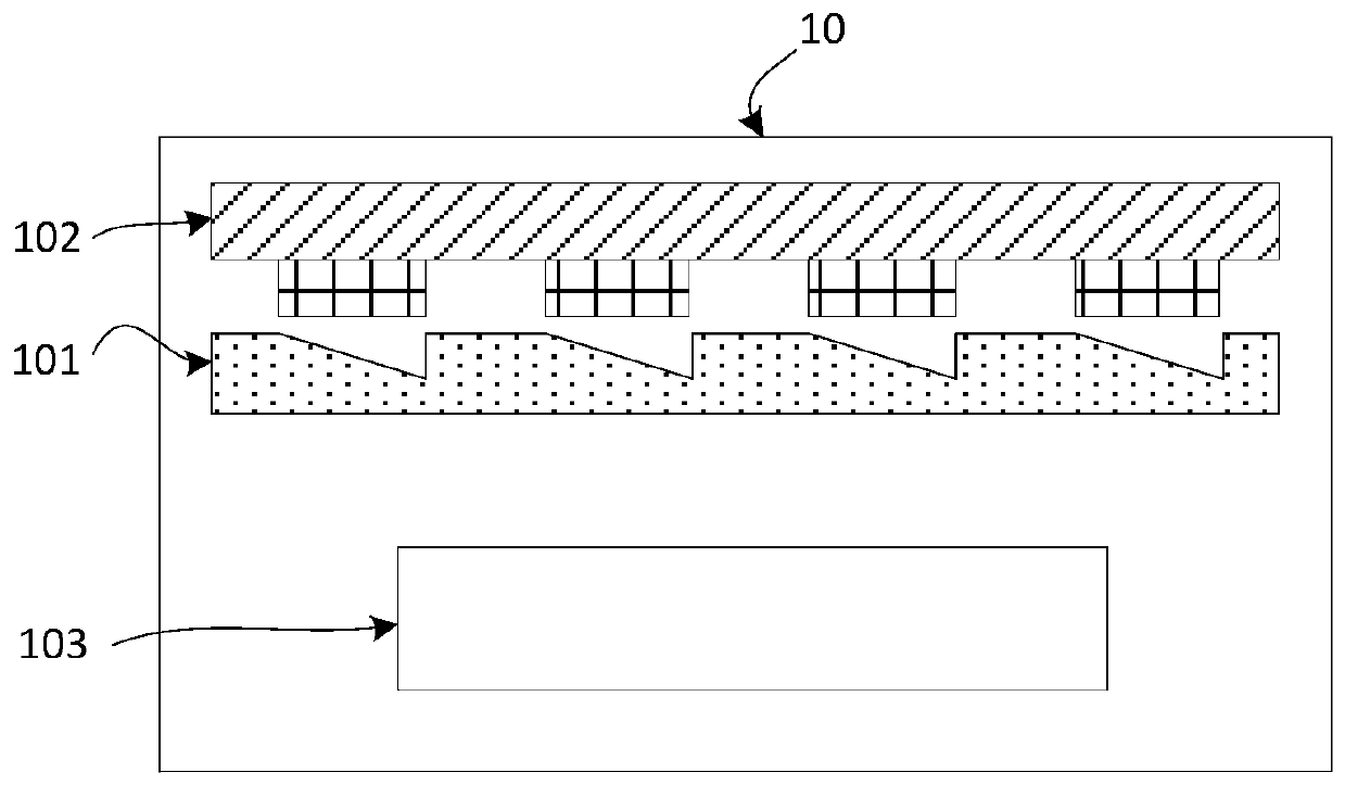
[0059] In order to solve the problem in the prior art that the consistency and repeatability of trace protein detection are poor due to the instability of the immune reaction process and the inconvenient effective control, Embodiment 1 of the present invention provides a protein detection system 10, please refer to figure 1 , the protein detection system 10 includes a microfluidic chip 101, a bipolar electrode chip 102 and a concentration determination component 103, wherein:
[0060] The microfluidic chip 101 includes a plurality of microwells arranged in an array, and the microwells are used to capture the solid-phase carrier in the sample to be tested; the sample to be tested includes: Solid phase carrier, solid phase carrier unbound with test protein and electrochemiluminescent material, electrochemical reaction solution;
[0061] The bipolar electrode chip 102 includes a plurality of electrode units arranged in an array, and when the electrode units are activated in the s...
Embodiment 2
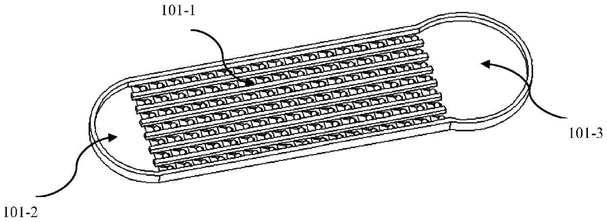
[0078] Embodiment 2 of the present invention provides a microfluidic chip, please refer to image 3 ,include:
[0079] The solid-phase carrier tiled area 101-1, the solid-phase carrier tiled area 101-1 includes a plurality of liquid diversion grooves, and micro-wells located at the bottom of the liquid diversion grooves, the micro-wells in the microfluidic Arranged in an array on the chip.
[0080] The solid phase carrier tiling area is designed as a two-layer structure. The upper layer is a liquid diversion groove structure with a diversion width of 5-50 μm and a diversion depth of 10-30 μm. The liquid in the sample loading area can pass through the gross suction of the diversion structure. Spread the liquid freely in the tiled area, and flow in a uniform direction. The lower layer is a microwell array structure, and each microwell can only accommodate one magnetic bead position. Under the action of the evaporation effect of the liquid, the magnetic beads in the liquid wil...
Embodiment 3
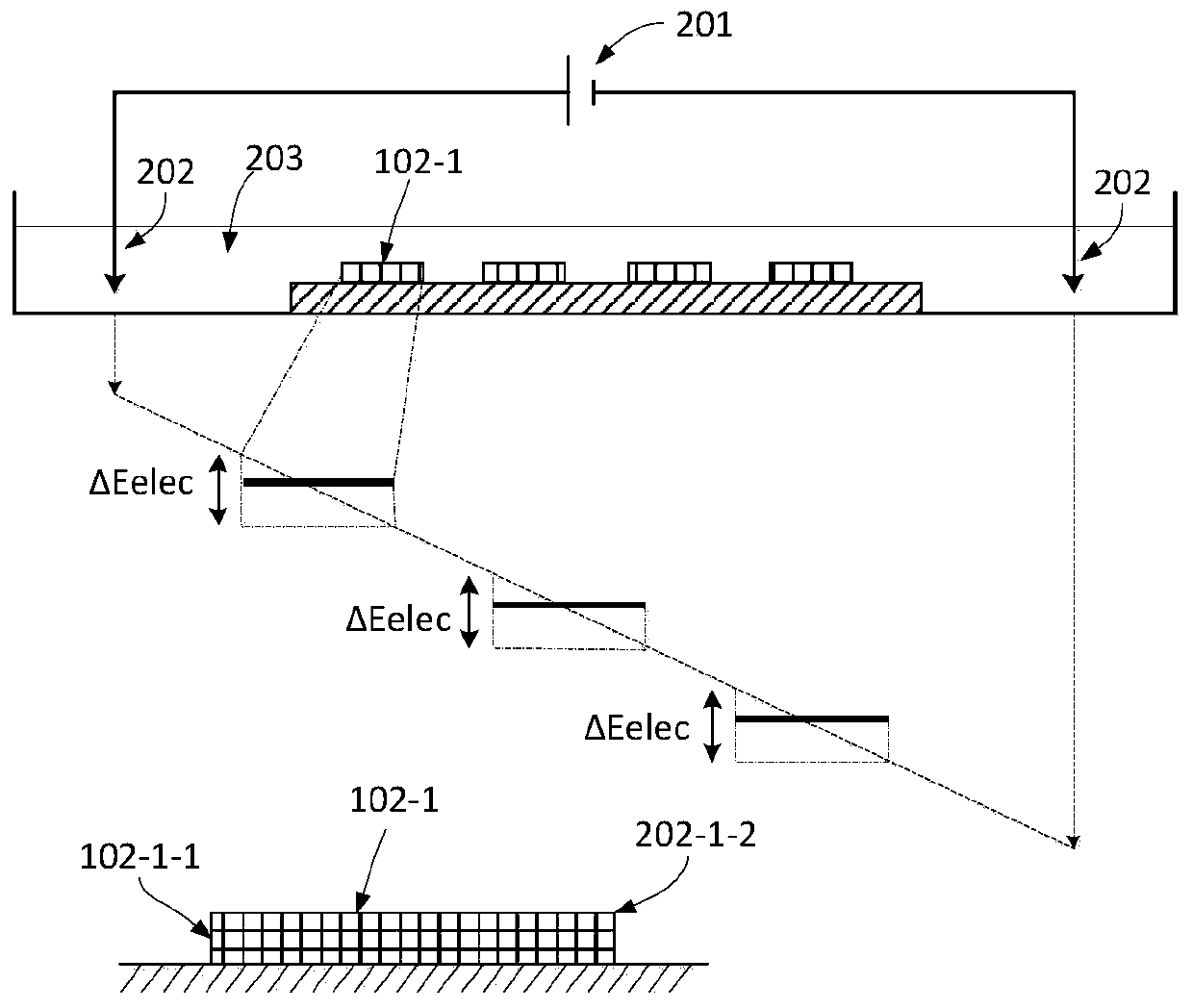
[0086] Embodiment 3 of the present invention provides a bipolar electrode chip 102, please refer to Figure 4 ,include:
[0087] A plurality of electrode units 102-1 arranged in an array, when the electrode units 102-1 are activated in the sample to be tested, electrochemically react with the electrochemiluminescence material and emit light;
[0088] The area of the anode end 102-1-2 of the electrode unit is smaller than the area of the cathode end 102-1-1.
[0089] The area of the anode end of the bipolar electrode is small, while the area of the cathode end is large. Since the total charge of the electrode is neutral, the current density of the anode will be higher and the luminous intensity will be stronger.
[0090] A preferred embodiment, in the technical solution proposed in Example 3 of the present invention, the cross-section of the electrode unit parallel to the electrode plate is triangular, such as Figure 4 As shown, one side of the triangle is the cathode,...
PUM
| Property | Measurement | Unit |
|---|---|---|
| particle diameter | aaaaa | aaaaa |
Abstract
Description
Claims
Application Information
 - R&D
- Intellectual Property
- Life Sciences
- Materials
- Tech Scout
- Unparalleled Data Quality
- Higher Quality Content
- 60% Fewer Hallucinations
Browse by: Latest US Patents, China's latest patents, Technical Efficacy Thesaurus, Application Domain, Technology Topic, Popular Technical Reports.
© 2025 PatSnap. All rights reserved.Legal|Privacy policy|Modern Slavery Act Transparency Statement|Sitemap|About US| Contact US: help@patsnap.com


