Waterwheel-like chain-box-type vertical fuel conveying device

A technology of conveying device and chain box, applied in the field of transmission, can solve the problems such as difficulty in jamming of spherical nuclear fuel elements, jamming of spherical nuclear fuel elements, large building area and space, etc.

Pending Publication Date: 2020-01-03
CHINERGY CO LTD
View PDF1 Cites 0 Cited by
  • Summary
  • Abstract
  • Description
  • Claims
  • Application Information

AI Technical Summary

Problems solved by technology

[0004] Disadvantage 1: The loading and unloading cycle of spherical nuclear fuel elements adopts helium pneumatic conveying
Under normal working conditions, the spherical nuclear fuel element needs to rely on the helium compressor to provide the power source for the pneumatic transmission during the pneumatic cycle transmission process. The lack of reliability of the helium compressor causes the spherical nuclear fuel element to lose its power source in the cycle, resulting in reactor failure. Passive shutdown; at the same time, in the process of pneumatic circulation transmission, the internal diameter of the pneumatic transmission pipe and the inner wall of the pipe weld are highly demanding and the inner wall is concave. As a result, the spherical nuclear fuel element cannot be transported and circulated, resulting in a passive shutdown of the reactor; the number of spherical nuclear fuel elements in the pneumatic conveying pipeline and the size deviation of the fuel pellets have different requirements on the pneumatic conveying pressure parameters, which intensifies the pressure parameters of the spherical nuclear fuel element. The stagnation and vibration in the pipeline lead to th

Method used


Image

  • Waterwheel-like chain-box-type vertical fuel conveying device
  • Waterwheel-like chain-box-type vertical fuel conveying device
  • Waterwheel-like chain-box-type vertical fuel conveying device

Examples


Embodiment Construction

[0025] The technical solutions of the present invention will be described in further detail below in conjunction with the accompanying drawings and embodiments.

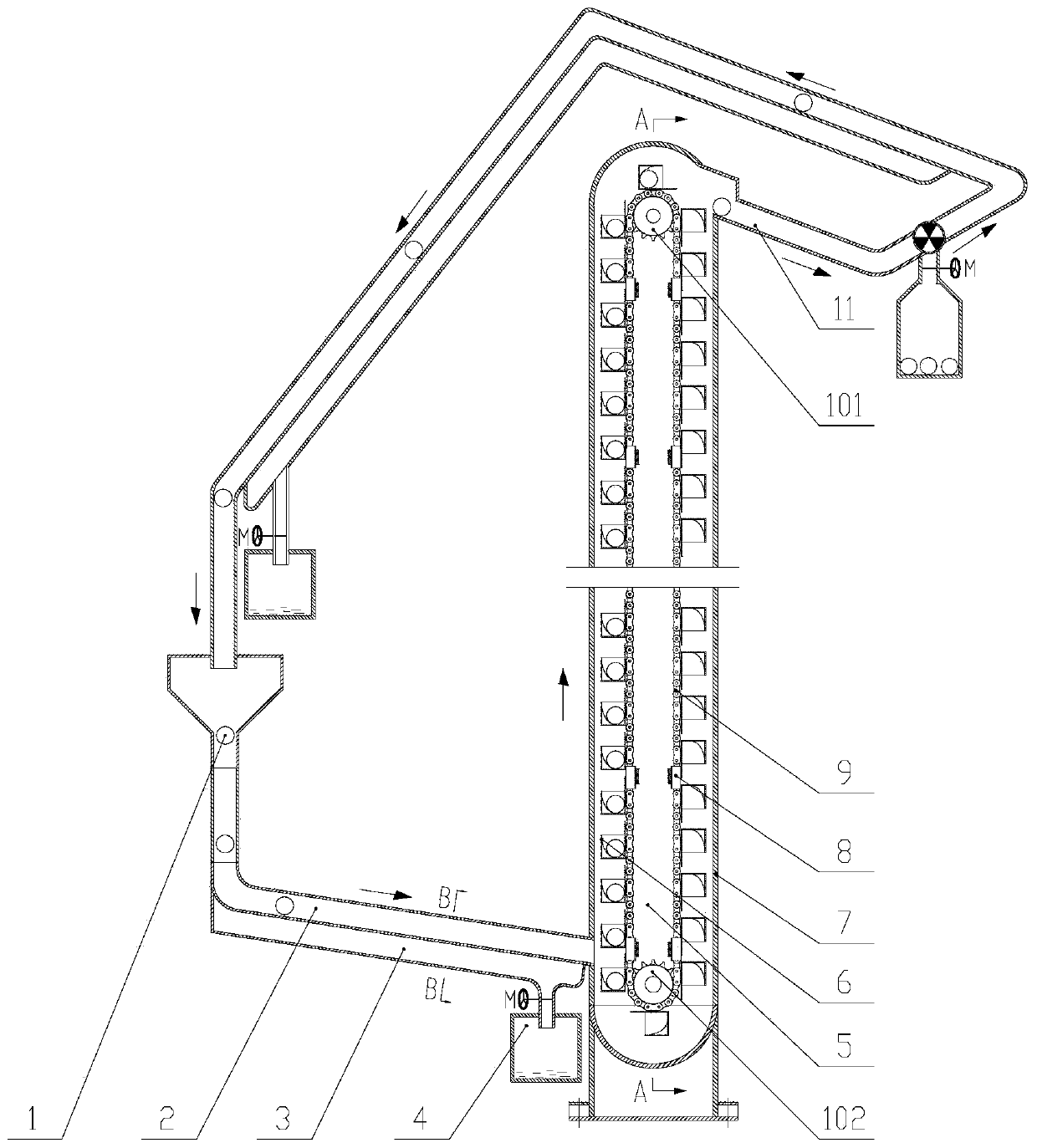
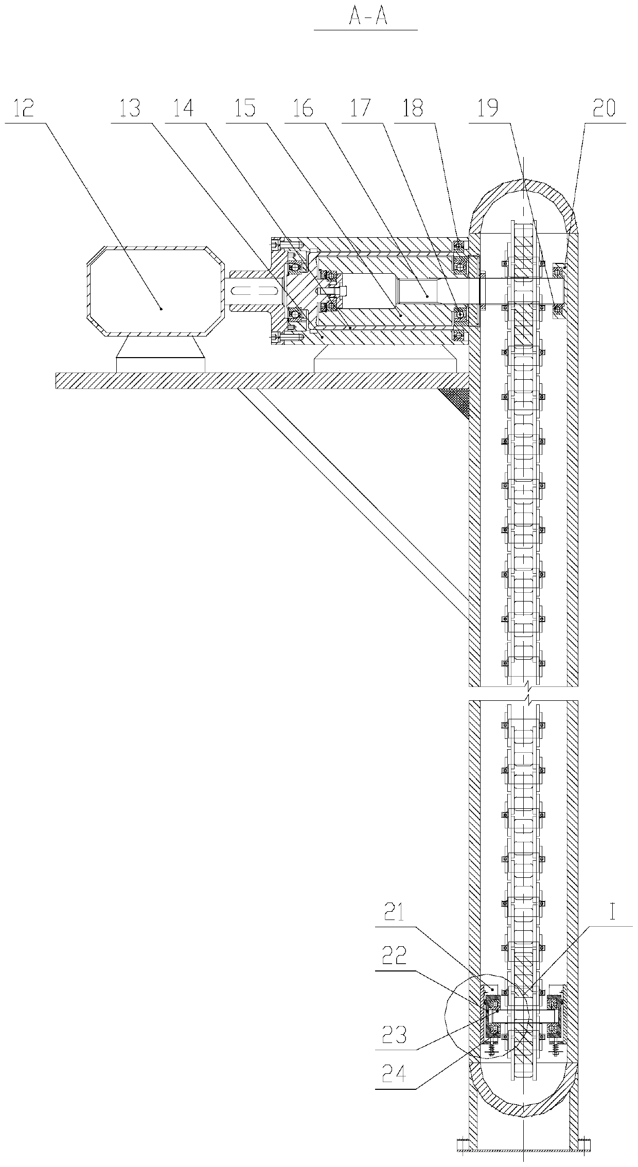
[0026] see figure 1 , is a schematic diagram of the overall structure of a water truck chain box type fuel vertical conveying device according to an embodiment of the present invention, which is used in a high temperature gas-cooled reactor nuclear power plant. The fuel vertical conveying device of the present embodiment comprises a sealed container 7 containing helium, a mechanical transmission part 5 located in the container 7, and a drive assembly located outside the container 7; the upper and lower ends of the container 7 are respectively aligned with the gravity The passive grooved raceways 11 and 2 are connected to form a loop, and the bottom of the grooved raceways 2 and 11 is provided with a dust conveying pipe 3 for collecting dust and debris falling through the grooved raceways. The end of conveying pipe 3...


PUM


Abstract

The invention provides a waterwheel-like chain-box-type vertical fuel conveying device. A mechanical transmission part of the device is arranged in a containing body; a driving component is arranged outside the containing body; the upper end and the lower end of the containing body are respectively connected with slotted roller paths. The mechanical transmission part comprises a driving wheel, a driven wheel, a driving chain, and a plurality of chain boxes fixed on the driving chain to hold spherical nuclear fuel elements; the driving wheel is driven by the driving component and drives the driven wheel to rotate by the driving chain; each chain box is a box with an open end; and each box body is provided with a centering guide plate for ensuring that the corresponding spherical nuclear fuel element is located at the center of the chain box. A side wall, in contact with the drive chain, at the open end of the box extends outwards to form a diverting plate for diverting the spherical nuclear fuel elements into the chain boxes or providing a rolling distance for enabling the spherical nuclear fuel elements to enter the slotted roller paths. Mesh between the drive chain and the drive wheels is ensured by correction pieces fixed to the inner side wall of the containing body. The device is reliable in operation, simple in structure and high in economy.

Description

technical field [0001] The invention is a water wheel chain box type fuel vertical conveying device, which is used in the loading and unloading cycle system of spherical nuclear fuel elements in high temperature gas-cooled reactor nuclear power plants, spent fuel unloading systems and new fuel injection systems or similar application fields such as petrochemical and electric power, and belongs to the field of transmission technology field. Background technique [0002] The loading and unloading cycle of spherical nuclear fuel elements in high-temperature gas-cooled reactor nuclear power plants needs to rely on helium compressors to provide the power source for pneumatic transportation required for the lifting of spherical nuclear fuel elements. Unloading and new fuel injection, during the pneumatic cycle transmission process, the spherical nuclear fuel element will continue to rub and collide with the inner wall of the pipeline, the unloading device, the broken ball separati...

Claims


Application Information

Patent Timeline
IPC IPC(8): G21C19/10G21C19/18G21C19/32
CPCG21C19/10G21C19/18G21C19/32Y02E30/30
Inventor 孟东旺
Owner CHINERGY CO LTD
Why Eureka
Try Eureka