Bonding device and bonding method

A fixed mechanism and fixed platform technology, applied in the manufacturing of electrical components, electrical solid-state devices, semiconductor/solid-state devices, etc. The effect of improving efficiency and quality, small heat affected area and easy control

Pending Publication Date: 2020-01-03
SHENZHEN HANHE INTELLIGENT MFG CO LTD
View PDF0 Cites 0 Cited by
  • Summary
  • Abstract
  • Description
  • Claims
  • Application Information

AI Technical Summary

Problems solved by technology

[0005] The technical problem to be solved by the present invention is to provide a bonding device and a bonding method for the above-mentioned defects of the prior art, which can solve the problem that polarizers and chip-on-chip films are easily damaged by high temperature through the heat dissipation of the pressure head, and solve the problem of laser The problem of poor penetration and heat accumulation, and solve the problem of poor processing effect and low excellent rate

Method used


Image

  • Bonding device and bonding method
  • Bonding device and bonding method
  • Bonding device and bonding method

Examples


Embodiment Construction

[0038] Now in conjunction with the accompanying drawings, the preferred embodiments of the present invention will be described in detail.

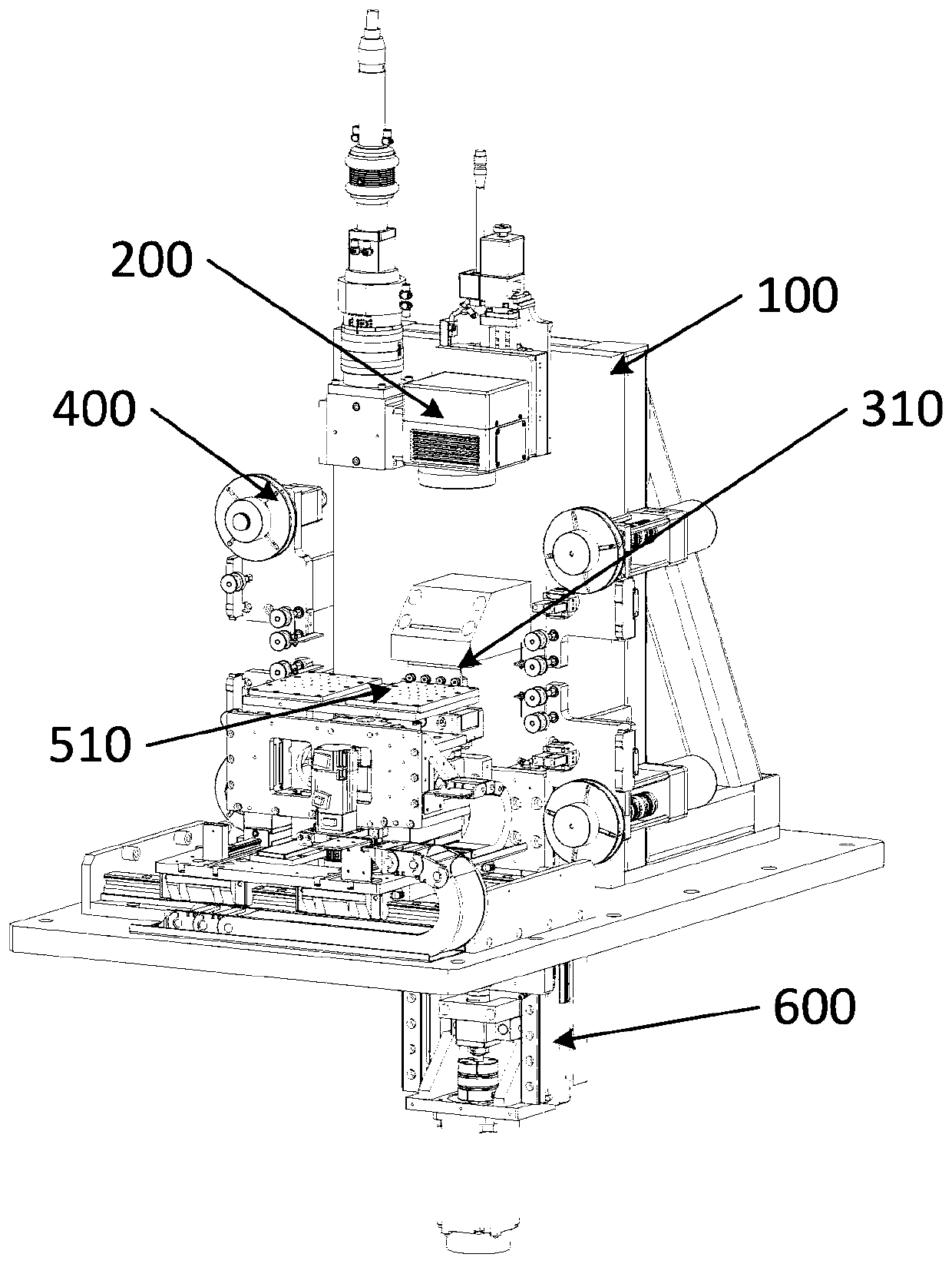
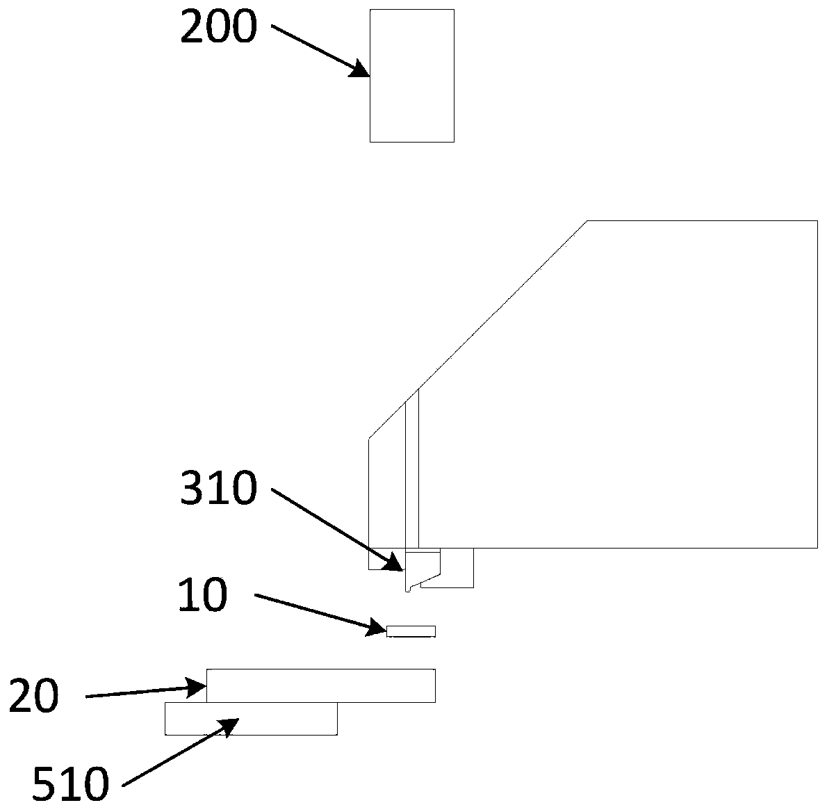
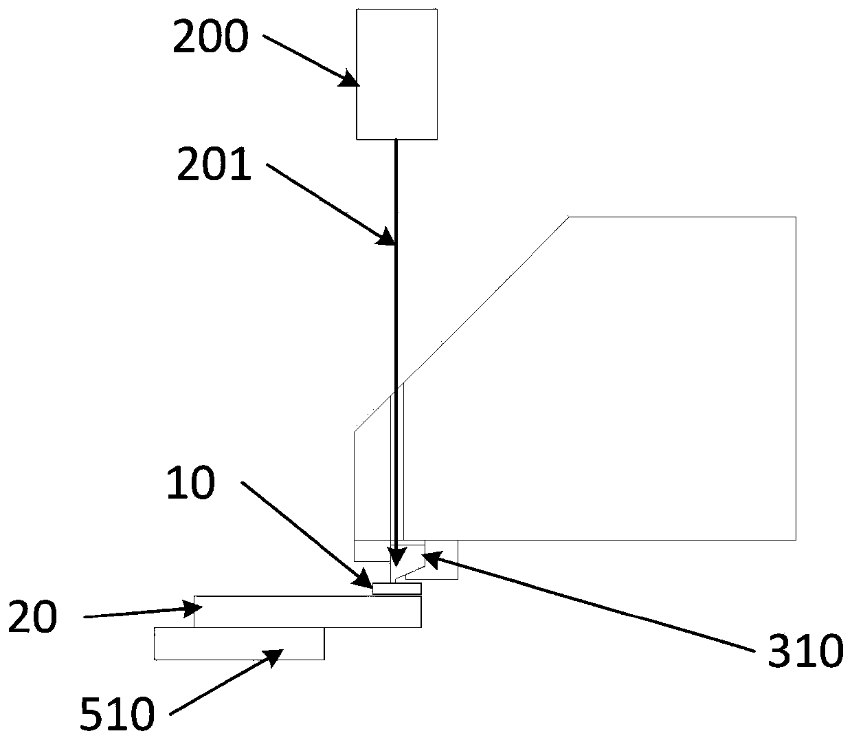
[0039] Such as Figures 1 to 3 As shown, the present invention provides a preferred embodiment of a bonding device based on a display panel.

[0040] A bonding device based on a product 20, the bonding device includes a laser 200, an indenter 310, a first buffer material fixing mechanism 400, a fixing platform and a pressing mechanism, and the fixing platform includes a fixing component 510 for fixing the product 20 , the material of the indenter 310 is a material with good light transmission and thermal conductivity; wherein, the pins of the product 20 are covered with a pre-pressed chip-on-chip film, and the pins of the product 20 are in contact with the An ACF is arranged between the COFs; and, the first buffer material fixing mechanism 400 clamps the buffer material 10 between the crimping surface of the pressure head 310 and the COF ...


PUM


Abstract

The invention relates to the field of bonding technology for display panel processing, specifically to a bonding device and a bonding method. The bonding device comprises a laser, a pressure head, a first buffer material fixing mechanism, a fixing platform and a pressing mechanism, wherein the fixing platform comprises a fixing assembly for fixing a product, and the pressure head is made of a material with light transmission performance and heat conductivity. Compared with the prior art, the invention has the following beneficial effects: the bonding device and the bonding method are designedto overcome the problem that a traditional heating mode is large in heat influence; and through heat dissipation of the pressure head, the temperature of a chip on film, a buffer material and other peripheral components is comprehensively reduced, ACF heating is not affected, and ACF heating is more uniform.

Description

technical field [0001] The invention provides the technical field of bonding for display panel processing, and in particular relates to a bonding device and a bonding method. Background technique [0002] With the continuous development of full-screen technology, the screen-to-body ratio is getting higher and higher, and the bonding area is getting narrower and narrower. In the traditional local pressure method, the indenter is heated by a heater. Because the distance between the indenter and the polarizer of the display panel is too close, the polarizer will be radiated by high temperature and damaged. At the same time, the heater heating method generally adopts constant temperature heating. The height control is better, and the heating is uniform. The disadvantage is that the temperature of the entire indenter and buffer material is relatively high, which has a great thermal impact on the panel components. [0003] In order to solve the above problem, laser heating is use...

Claims


Application Information

Patent Timeline
Patent Type & Authority Applications(China)
IPC IPC(8): H01L21/603
CPCH01L24/75H01L24/83H01L2224/75266H01L2224/75312H01L2224/75502H01L2224/83203H01L2224/83224
Inventor 李治蒙吴铭郝玉亮万义兵李宁高云峰
Owner SHENZHEN HANHE INTELLIGENT MFG CO LTD
Why Eureka
Try Eureka