Planar array near-field multipoint focusing system and method based on time reversal

A planar array and time-reversal technology, applied in transmission systems, radio transmission systems, microwave therapy, etc., can solve problems such as inability to focus, low optimization rate, and inability to meet high-efficiency requirements, so as to reduce the number of optimization iterations and speed up optimization process, the effect of reducing redundancy

Active Publication Date: 2020-01-03
UNIV OF ELECTRONIC SCI & TECH OF CHINA
View PDF5 Cites 8 Cited by
  • Summary
  • Abstract
  • Description
  • Claims
  • Application Information

AI Technical Summary

Problems solved by technology

In 2014, an application for an invention patent with the patent number 201410440116.7 disclosed a space electromagnetic field shaping method based on time-reversed electromagnetic wave transmission. With the help of the space-time focusing principle of time-reversed electromagnetic waves, the electromagnetic wave is generated in the space area. Energy is concentrated in a specific shape range. Although this is the regulation of electromagnetic waves in the near field, its research cannot precisely focus energy on a target point; in 2018, an application for an invention patent with patent number 201810580750.9, A multi-target selective wireless energy transmission method and device based on focused waves is disclosed, and an optimiz

Method used


Image

  • Planar array near-field multipoint focusing system and method based on time reversal
  • Planar array near-field multipoint focusing system and method based on time reversal
  • Planar array near-field multipoint focusing system and method based on time reversal

Examples


Embodiment Construction

[0058] The technical solution of the present invention is described in detail below in conjunction with accompanying drawing and example, so that understand feature and advantage of the present invention more clearly.

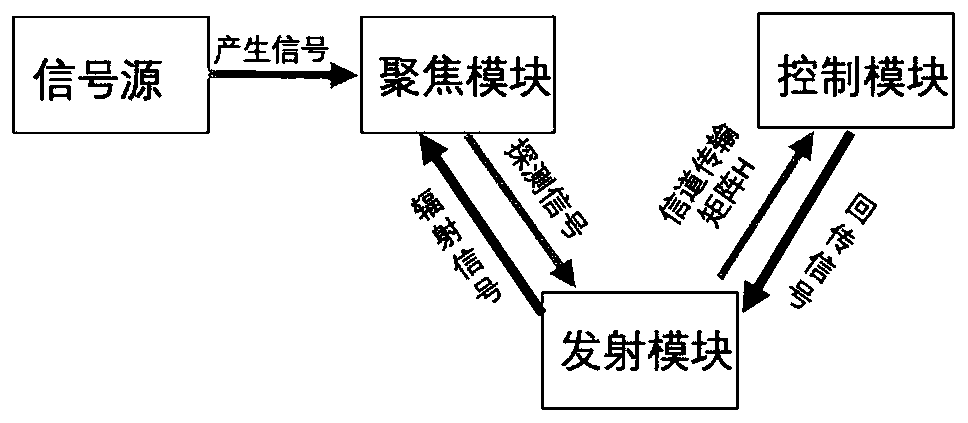
[0059] A planar array near-field multi-point focusing system based on time reversal, including

[0060] The signal source is used to generate the channel detection signal. The excitation signal of the example of the present invention adopts a sinusoidal signal with a bandwidth of 1-4GHz and a center frequency of 2.45GHz.

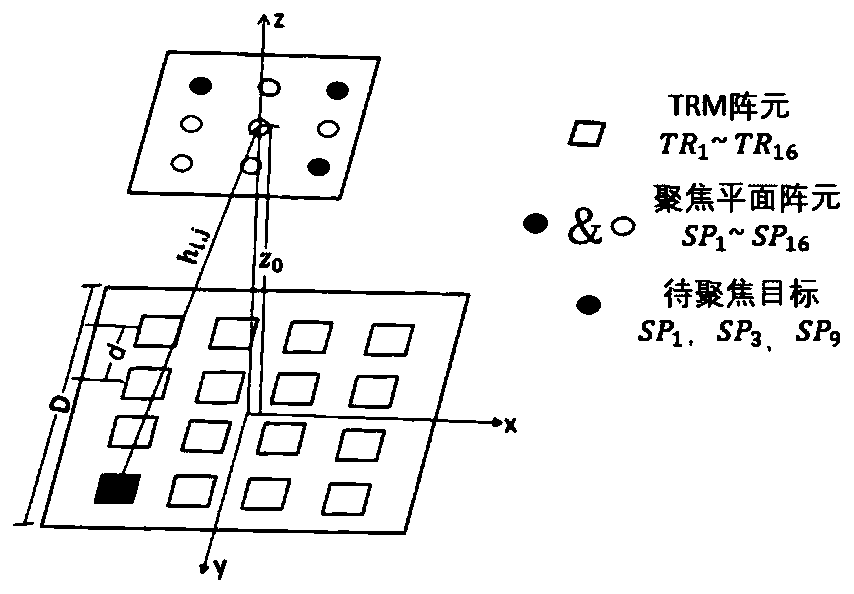
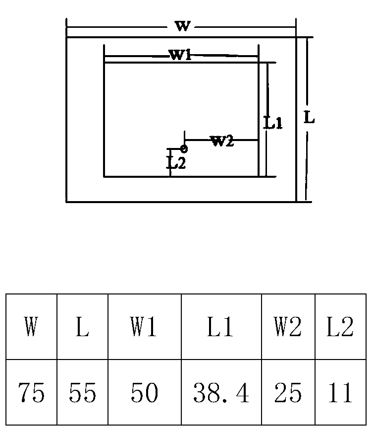
[0061] The transmitting module includes a transmitting planar array composed of 4x4 patch antenna elements with a size of 75mmx55mm and a spacing of 0.8 times the wavelength. Its center frequency is 2.45GHz and the bandwidth is 500MHz. It is used to receive detection signals and send TRM return signals. The 16 TR antenna elements are numbered Tx from left to right and from top to bottom 1 ~Tx 16 ,Such as image 3 shown.

[0062] The contr...


PUM


Abstract

The invention discloses a planar array near-field multipoint focusing system and method based on time reversal, and relates to the field of electromagnetic wave regulation and control. The planar array near-field multipoint focusing system comprises a signal generator for generating a channel detection signal, a transmitting module which is used for receiving the detection signal and transmittinga TRM return signal, a control module which is used for regulating and controlling the return signal, and a focusing module which transmits a detection signal. According to the planar array near-fieldmultipoint focusing system, SVD decomposition is utilized to represent a focusing field receiving signal as linear superposition of a plurality of orthogonal sub-signals so as to avoid redundancy caused by superposition of non-orthogonal signals; through threshold discrimination, a part of sub-channels are discarded, and the number of optimization variables is reduced, and the optimization speedis increased; a power fluctuation threshold is set to improve the transmission efficiency; and the energy ratio of each focus point is regulated and controlled by changing the power distribution ratio. Multi-point focusing can be generated in a near field with extremely uneven electromagnetic field intensity distribution according to a preset energy ratio, and the problems of microwave thermal therapy and multi-target selective wireless energy transmission can be effectively solved.

Description

technical field [0001] The invention belongs to the field of space propagation and control of electromagnetic waves, and in particular relates to a planar array near-field multi-point focusing system and method based on time inversion. Background technique [0002] With the continuous expansion of the application range of electromagnetic waves, for example, microwave hyperthermia, biological effect research, wireless energy transmission, encrypted communication, microwave cutting, etc., these applications all require the ability to precisely focus electromagnetic waves at a fixed position for Act on a specific object. In the field of electromagnetism, there are a lot of researches on the propagation and regulation of electromagnetic waves. [0003] Among them, beamforming is to make the radiation pattern of the far-field area of ​​the antenna array into a specific beam by rationally designing the excitation amplitude and phase of each array element of the antenna array, the...

Claims


Application Information

Patent Timeline
IPC IPC(8): H04B7/0426H02J50/23A61N5/02G06F17/16
CPCA61N5/02G06F17/16H04B7/0426H02J50/23
Inventor 刘要红赵德双包金龙钟成
Owner UNIV OF ELECTRONIC SCI & TECH OF CHINA
Why Eureka
Try Eureka