Laser radar, autonomous mobile robot and intelligent vehicle
A technology of lidar and laser beam, applied in the field of detection, can solve problems such as high cost and complex manufacturing process
- Summary
- Abstract
- Description
- Claims
- Application Information
AI Technical Summary
Problems solved by technology
Method used
Image

Examples
Embodiment 1
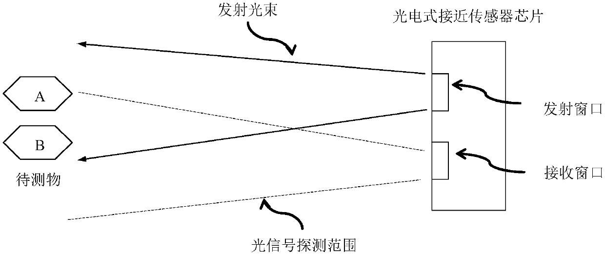
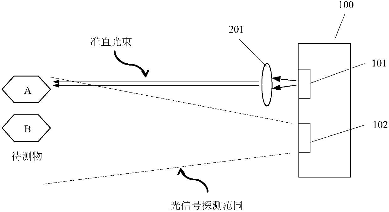
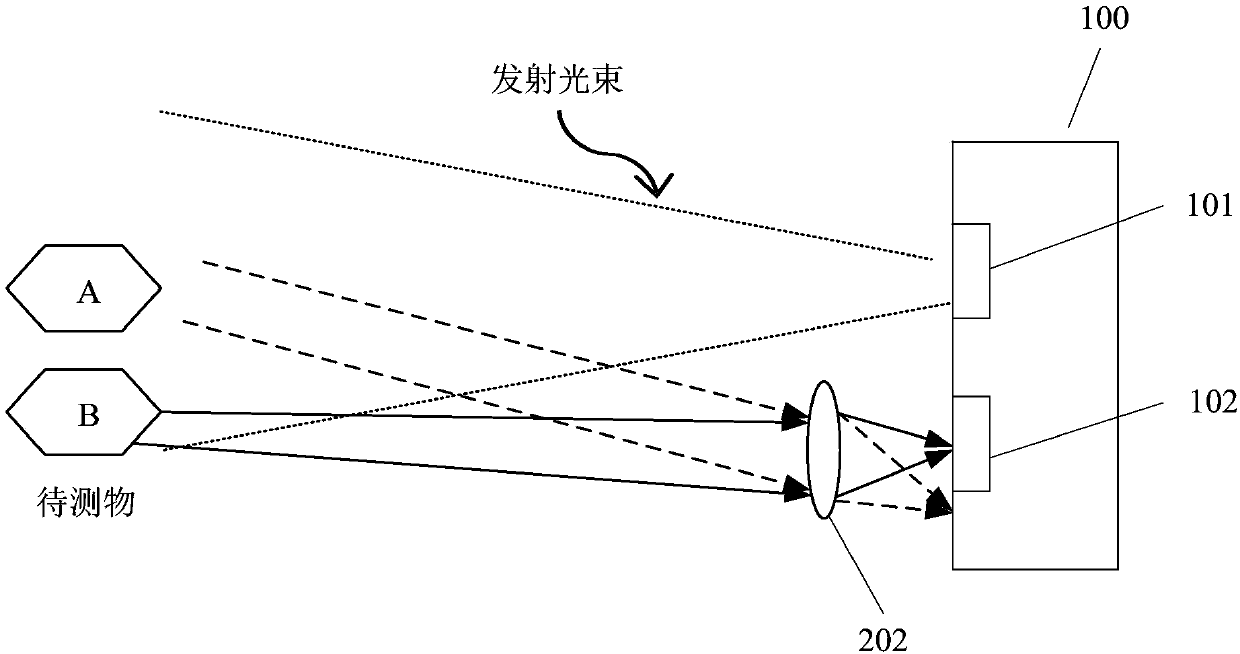
[0040]An embodiment of the present invention provides a laser radar, including a ranging unit; the ranging unit includes a photoelectric proximity sensor chip and a collimating and focusing element, and the collimating and focusing element is arranged in the ranging optical path of the ranging unit; wherein, the ranging The optical path includes an emitting optical path between the emitting window of the photoelectric proximity sensor chip and the object to be measured, and a receiving optical path between the object to be measured and the receiving window of the photoelectric proximity sensor chip. The working principle of the laser radar is as follows: the distance measuring unit emits a laser beam through the emission window, and the laser beam is collimated or focused by the collimating and focusing element and reflected by the object to be measured, and then received by the receiving window to realize the distance measurement of the object to be measured .
[0041] Specif...
Embodiment 2
[0068] An embodiment of the present invention provides an autonomous mobile robot, including the laser radar in the first embodiment above. Specifically, the autonomous mobile robot may be, but not limited to, a sweeping robot. The lidar can be used for local landmark detection and map matching of autonomous mobile robots, establishment of terrain maps during travel, and obstacle detection.
[0069] In the embodiment of the present invention, the laser radar includes a ranging unit; the ranging unit includes a photoelectric proximity sensor chip and a collimating and focusing element, and the collimating and focusing element is arranged in the ranging optical path of the ranging unit; wherein, the ranging optical path includes a photoelectric The emitting optical path between the emitting window of the type proximity sensor chip and the object to be measured and the receiving optical path between the object to be measured and the receiving window of the photoelectric proximity...
Embodiment 3
[0071] An embodiment of the present invention provides a smart vehicle, including the laser radar in the first embodiment above. The lidar can be used for local road sign detection and map matching of intelligent vehicles, establishment of traveling topographic maps, obstacle detection, side-view or rear-view ranging sensing, high-precision gesture recognition, etc. for automatic car parking systems.
[0072] In the embodiment of the present invention, the laser radar includes a ranging unit; the ranging unit includes a photoelectric proximity sensor chip and a collimating and focusing element, and the collimating and focusing element is arranged in the ranging optical path of the ranging unit; wherein, the ranging optical path includes a photoelectric The emitting optical path between the emitting window of the type proximity sensor chip and the object to be measured and the receiving optical path between the object to be measured and the receiving window of the photoelectric ...
PUM
 Abstract
Description
Claims
Application Information
 - R&D
- Intellectual Property
- Life Sciences
- Materials
- Tech Scout
- Unparalleled Data Quality
- Higher Quality Content
- 60% Fewer Hallucinations
Browse by: Latest US Patents, China's latest patents, Technical Efficacy Thesaurus, Application Domain, Technology Topic, Popular Technical Reports.
© 2025 PatSnap. All rights reserved.Legal|Privacy policy|Modern Slavery Act Transparency Statement|Sitemap|About US| Contact US: help@patsnap.com