Integrated liquid treatment device

A liquid treatment, integrated technology, applied in filtration treatment, special treatment targets, oxidized water/sewage treatment, etc., can solve the problems of needing staff on duty, poor oil removal effect, low treatment efficiency, etc., to improve the oil-water separation effect. , easy maintenance, good treatment effect

Pending Publication Date: 2020-01-10
杭州路弘科技有限公司
View PDF0 Cites 0 Cited by
  • Summary
  • Abstract
  • Description
  • Claims
  • Application Information

AI Technical Summary

Problems solved by technology

When removing miscellaneous oil, the method of manually adjusting the liquid level of the U-shaped tube is adopted. When the equipment is running, the staff needs to be on duty to facilitate the timely removal of oil from the oil-water separator. , the discharged oil more or less carries waste liquid
Although the steel belt degreasing machine can realize automatic degreasing, the degreasing effect of the steel belt degreasing machine is poor, the treatment efficiency is low, and the discharged oil also carries too much waste liquid

Method used


Image

  • Integrated liquid treatment device
  • Integrated liquid treatment device
  • Integrated liquid treatment device

Examples


Embodiment 1

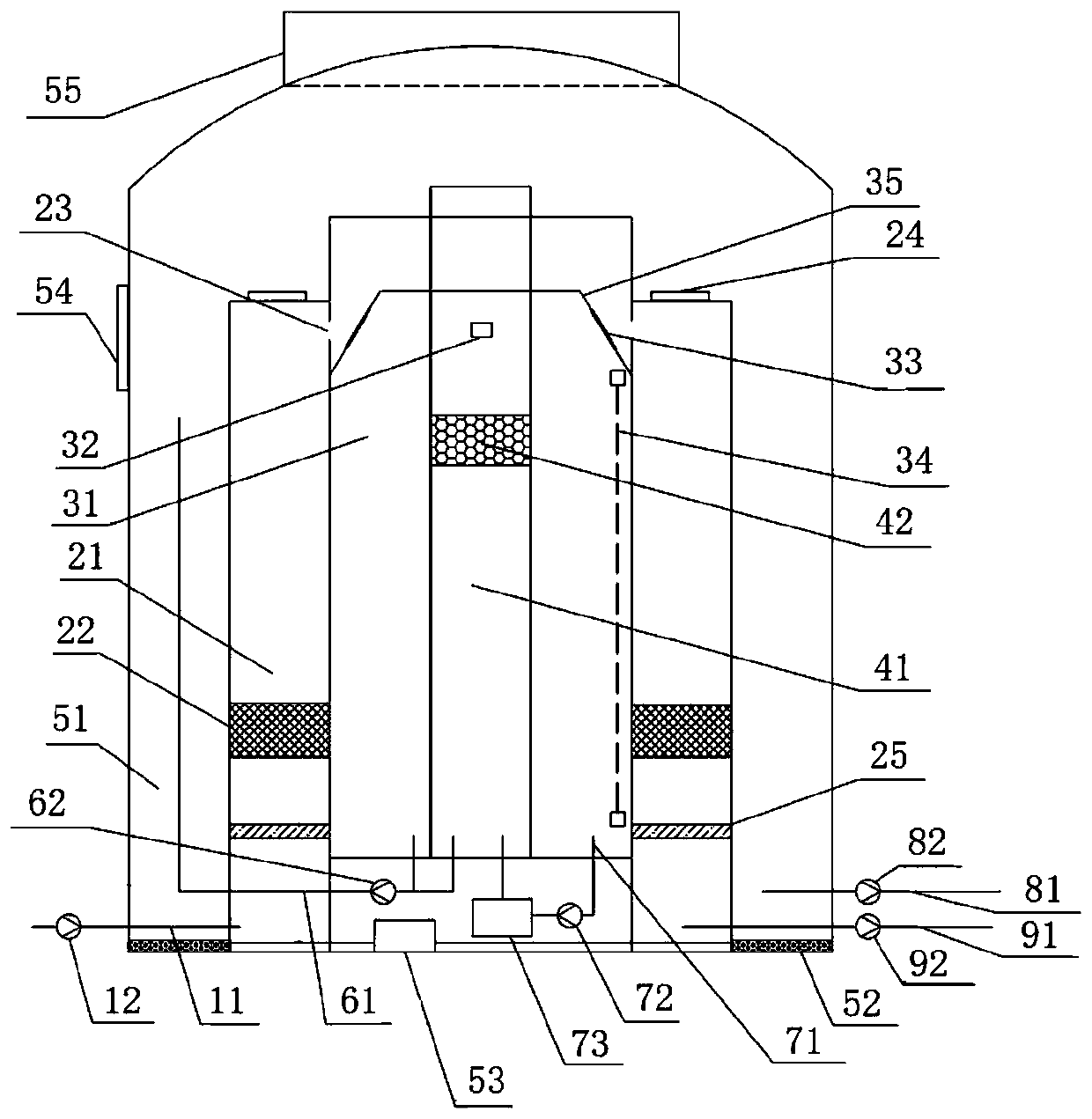
[0040] figure 1 Schematically presents a simplified structural diagram of an integrated liquid treatment device in an embodiment of the present invention, as shown in figure 1 As shown, the integrated liquid handling device includes:

[0041] Liquid inlet pipeline 11 and pump 12, liquid outlet pipeline 81 and pump 82;

[0042] A plurality of cavities surrounding and mutually isolated from the inside to the outside, the multiple cavities include a first cavity 21, a second cavity 31 and a third cavity 41; the liquid inlet pipe 11 communicates with the first cavity 21, so The outlet pipe 91 communicates with the second chamber 31;

[0043] filter media 22, 25, the filter media are arranged in the first cavity 21, and are downstream of the liquid inlet pipe 11 of the liquid flow path;

[0044] A baffle 35, the baffle 35 is obliquely arranged on the upper part of the second chamber 31, and has a through hole 33, the baffle 35 at the lower part of the through hole 33 and the side ...

Embodiment 2

[0056] The application example of the integrated liquid treatment device according to the embodiment of the present invention is, for example, oil-water separation in the treatment of cutting fluid, release agent, and degreasing bath liquid.

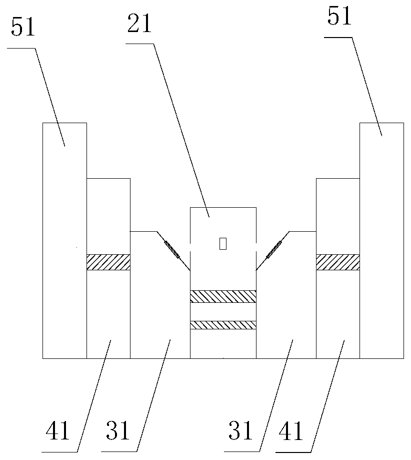
[0057] In this application example, if figure 1 As shown, the four cavities surrounding and isolated from the inside to the outside are concentrically distributed, which are the third cavity 41, the second cavity 31, the first cavity 21 and the fourth cavity 51; the liquid inlet pipe 11 and the The bottom in the first chamber 21 is connected, and the liquid outlet pipe 81 is directly connected with the fourth chamber and indirectly connected with the second chamber 31;

[0058] In the first chamber 21, the secondary filter media 22, 25 are arranged in the annular first chamber 21, and are successively (coarse filtration first, then fine filtration) downstream of the liquid inlet pipeline 11 of the liquid flow path; the first chamber The...

Embodiment 3

[0064] The application example of the integrated liquid treatment device according to the embodiment of the present invention is, for example, oil-water separation in the treatment of cutting fluid, release agent, and degreasing bath liquid. The difference with embodiment 2 is:

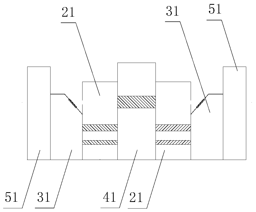
[0065] Such as figure 2 As shown, the four cavities surrounding and isolated from each other and concentrically distributed from the inside to the outside are the first cavity 21 , the second cavity 31 , the third cavity 41 and the fourth cavity 51 in sequence.


PUM


Abstract

The invention provides an integrated liquid treatment device. The integrated liquid treatment device comprises a liquid inlet pipeline, a liquid outlet pipeline, a plurality of cavities surrounded from inside to outside and isolated from each another, filter mediums, baffling bodies, an oil-water separation unit and liquid discharging ports, wherein the multiple cavities comprise first cavities, second cavities and third cavities; the filter mediums are arranged in the first cavities and are located downstream of the liquid inlet pipeline of a liquid flow path; the baffling bodies are obliquely arranged in the upper parts of the second cavities and provided with through holes, the baffling bodies on the lower parts of the through holes and the side walls of the first cavities form a spacefor accommodating liquid, and oleophylic hydrophobic films are arranged on the through holes; overflow ports are formed in the walls, close to the second cavities, of the first cavities, and the through holes face the entered liquid through the overflow ports; the liquid in the second cavities enters the third cavities through the oil-water separation unit; the liquid in the third cavities overflows and enters the second cavities through the through holes; and the liquid discharging ports are formed in the side walls and/or baffling bodies. The integrated liquid treatment device has the advantages of compact structure, small size and the like.

Description

technical field [0001] The present invention relates to liquid separation, and in particular to an integrated liquid treatment device. Background technique [0002] Industrial oily wastewater contains organic substances harmful to the environment such as oil, surfactants and organic additives, so it cannot be discharged arbitrarily without treatment. Industrial oily wastewater is recycled after oil-water separation or discharged after treatment up to standard, which are all environmental protection measures for industrial oily wastewater treatment. Machining cutting fluid is a metalworking fluid used for cooling and lubricating during metal cutting, cutting, grinding and other processing processes. It has a wide variety and complex composition, usually including base oil, emulsifier, antirust agent and so on. Cutting fluid has the functions of cooling, lubricating, cleaning and rust prevention during the processing of metals and their alloys. The waste cutting fluid used i...

Claims


Application Information

Patent Timeline
Patent Type & Authority Applications(China)
IPC IPC(8): C02F9/04
CPCC02F1/001C02F1/40C02F1/44C02F1/78C02F7/00C02F9/00C02F2303/04C02F2303/16
Inventor 闻路红杨晓东王明琼叶汉龙郭超伍恒汉
Owner 杭州路弘科技有限公司
Why Eureka
Try Eureka