Wind and water combined slag cooler for fluidized bed

A slag cooler and fluidized bed technology, applied in the field of slag cooling and discharging devices, can solve the problems of poor cost performance of the slag cooler, small slag discharge, high slag discharge temperature, etc., and achieve less operation failure, large slag discharge, cooling slag swift effect

Pending Publication Date: 2020-01-10
冯大勇
View PDF0 Cites 4 Cited by
  • Summary
  • Abstract
  • Description
  • Claims
  • Application Information

AI Technical Summary

Problems solved by technology

[0007] In order to overcome the phenomenon of coking, slag blockage and deformation of the heating surface of the fluidized bed air-water slag cooler, and at the same time overcome the small slag output of the drum slag cooler, the high slag discharge temperature, the serious environmental protection problems of the ash and slag leakage site, and other forms of cold slag The present invention provides a novel fluidized bed wind-water combined slag cooler, which eliminates the phenomenon of coking and slag blocking, is not limited by the particle size of the bottom slag, and is easy to control the slag in and out, and can achieve large output (above 40T / H ) continuous and stable operation

Method used


Image

  • Wind and water combined slag cooler for fluidized bed
  • Wind and water combined slag cooler for fluidized bed
  • Wind and water combined slag cooler for fluidized bed

Examples


Embodiment Construction

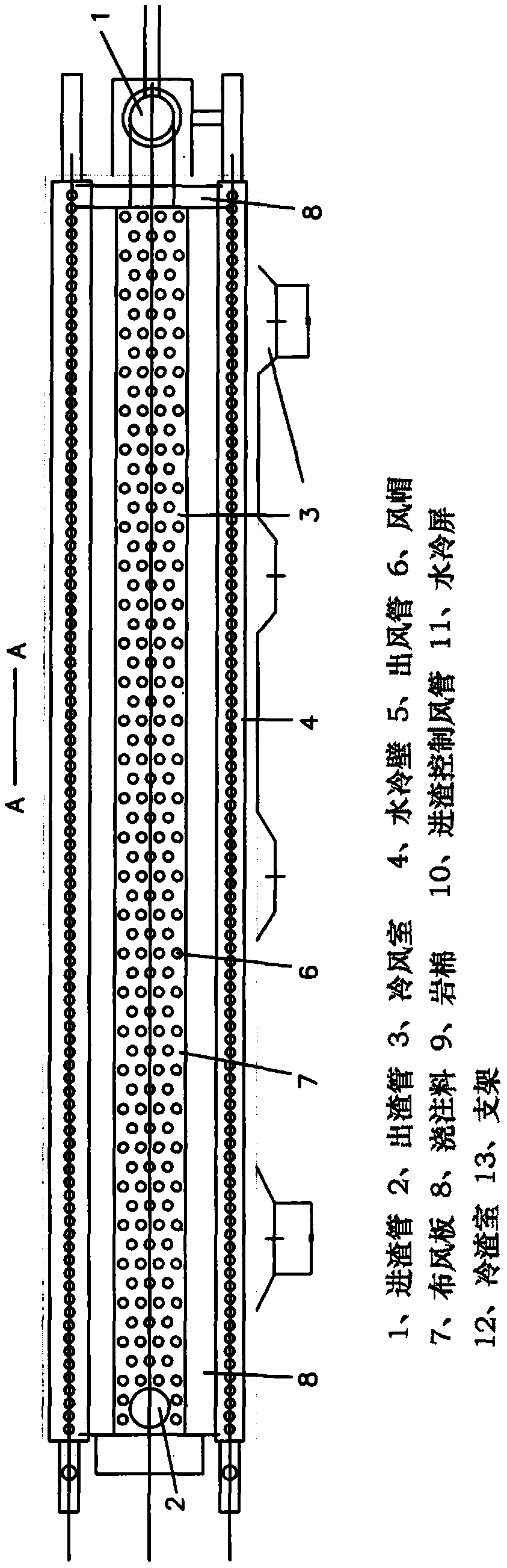
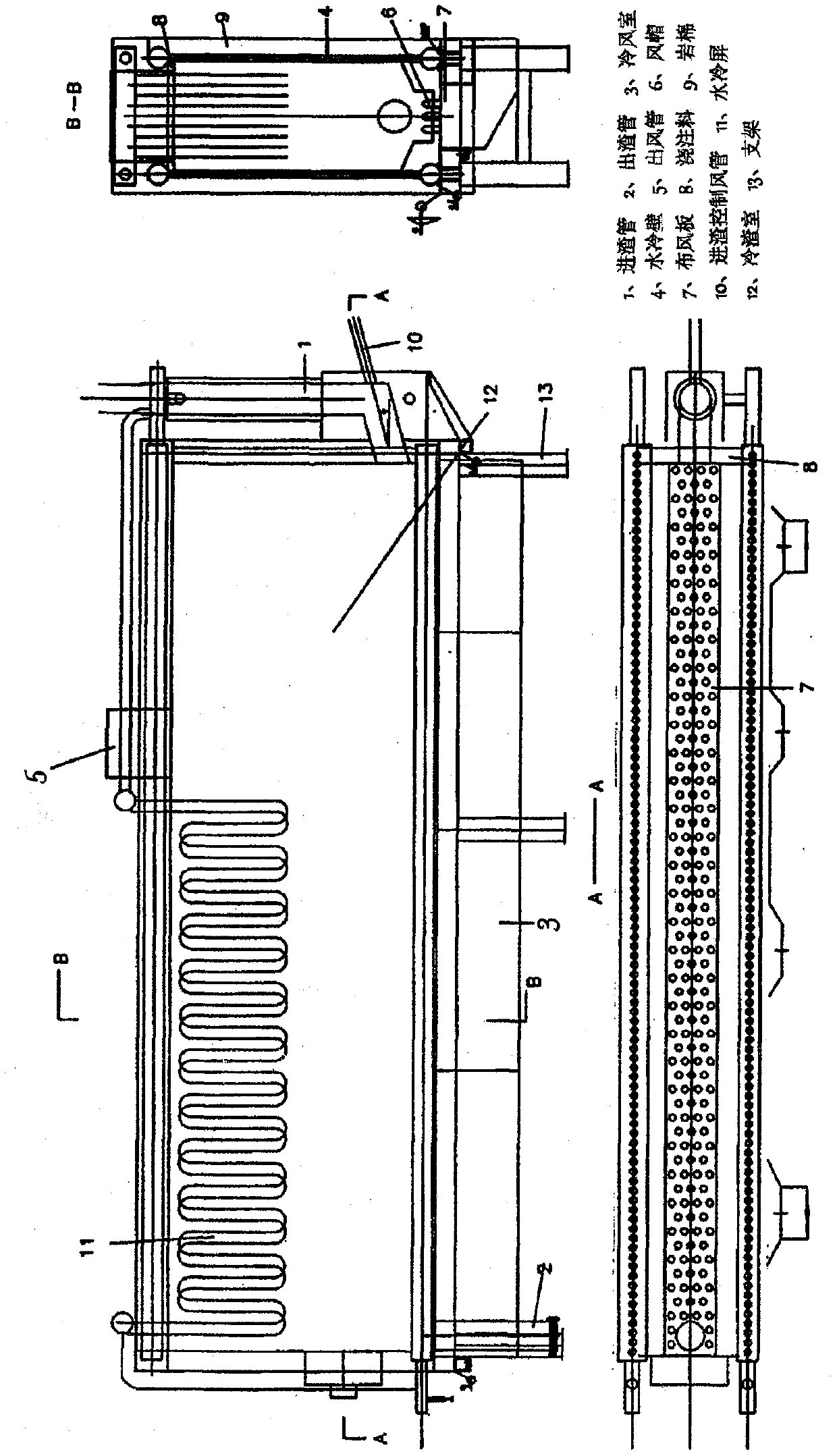
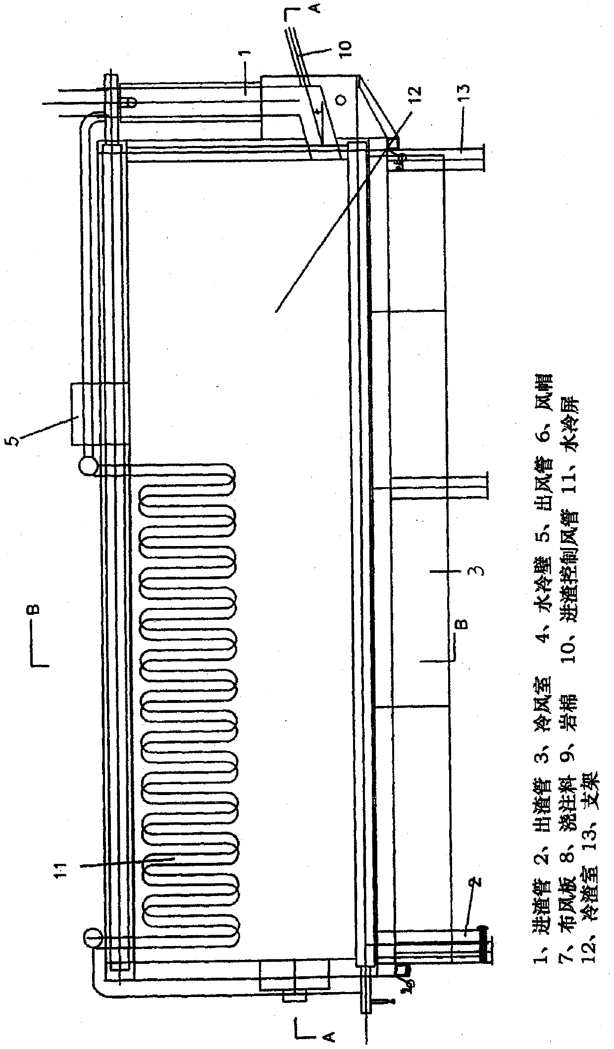
[0046] 1. The air distribution plate is made of 20#G by laser cutting and opening, and the base of the air cap is welded.

[0047] 2. The cold air chamber under the air distribution plate is sheared and welded by steel plates, and connected to the air inlet pipe and valve.

[0048] 3. The water cooling wall on the air distribution plate is composed of membrane tubes. The wear plate is machined from flat iron and welded to the water wall.

[0049] 4. The hood is casted by alloy, installed on the base of the air distribution plate, and then poured with castables.

[0050] 5. The slag inlet pipe and the slag outlet pipe are respectively welded to the slag inlet side plate of the slag cooler and the slag outlet of the air distribution plate.

[0051] 6. The hot air return pipe is welded on the top of the slag cooler

[0052] 7. Complete the welding and installation of other shells and brackets.


PUM


Abstract

The invention provides a wind and water combined slag cooler for a fluidized bed. The wind and water combined slag cooler is mainly used as a bottom slag cooling and discharging device for a boiler ofa circulating fluidized bed. Coking and slag blocking phenomena of the slag cooler for the fluidized bed are eliminated, the operation of the wind and water combined slag cooler is not limited by theparticle size of bottom slag, and slag inlet and outlet control is simple and convenient. First, a material discharge opening or an accident slag discharge opening is not formed in a slag inlet high-temperature area of the slag cooler in any forms, a whole wind-distribution plate is complete and uniform from a slag inlet to a slag outlet, and only one slag outlet is formed to prevent the coking phenomenon due to a bad fluidizing effect of the high-temperature area; second, wind caps are arranged in a crossed manner in the wind-distribution plate, small holes in the wind caps are inclined downwards by a certain angle, and the diameters of the small holes of the wind caps are 6-8 mm; third, the interior of the slag cooler is a complete cavity, and is not divided by a partition wall; fourth,wind control is adopted in the aspect of slag inlet control, and a slag inlet pipe section connected with the slag cooler forms an inclined angle of 14-25 degrees with the horizontal plane; and fifth, a water-cooled wall is prevented from being worn by a wear-resistant sheet, and spraying is performed on scenes to resist wear.

Description

[0001] a technical field [0002] The invention relates to a slag cooling and discharging device, which is mainly used as bottom slag cooling and discharging equipment of a circulating fluidized bed boiler. At the same time, it is suitable for the cooling of granular materials in energy, chemical, pharmaceutical, food, light industry, mining and metallurgy and other industrial sectors, and also suitable for powdery and granular materials in chemical, pharmaceutical, food, dehydrated vegetables, grain, minerals and other industries. drying and sorting. [0003] Two background technology [0004] my country's circulating fluidized bed boiler power generation started in 1996 and entered the supercritical era in 2013. Due to its advantages in comprehensive utilization of resources, circulating fluidized bed boilers have replaced pulverized coal boilers and become a trend in the thermal power generation industry. However, it is difficult to increase the boiler capacity due to the ...

Claims


Application Information

Patent Timeline
Patent Type & Authority Applications(China)
IPC IPC(8): F23C10/24
CPCF23C10/24
Inventor 冯大勇
Owner 冯大勇
Why Eureka
Try Eureka