Efficient energy-saving environment-friendly calcium carbide furnace

A high-efficiency, energy-saving, and environment-friendly technology, applied in the drying of solid materials, dryers, and drying of granular materials, can solve the problems of equipment cleanliness reduction, resource waste, and impact, and achieve the effect of calcium carbide quality assurance and reduction of raw material waste

Active Publication Date: 2020-01-14
HWASU
View PDF6 Cites 0 Cited by
  • Summary
  • Abstract
  • Description
  • Claims
  • Application Information

AI Technical Summary

Problems solved by technology

[0002] Calcium carbide is an inorganic compound and a colorless crystal. The industrial product is a gray-black block. When the calcium carbide furnace prepares calcium carbide, a large amount of high-heat waste gas will be generated. The direct discharge of high-heat waste gas will not only cause serious environmental pollution, but also cause resources (heat energy etc.), the existing calcium carbide furnace has low preparation efficiency, high efficiency, adequacy, and uniformity cannot be guaranteed. When the calcium carbide furnace is working, raw materials will inevitably adhere to the inner end wall of the furnace body, and the adhesion of raw materials Attachment will not only cause waste of resources, but also reduce the cleanliness of the equipment, which will affect the subsequent preparation process of calcium carbide. The size of raw material particles has a direct impact on the quality of the prepared calcium carbide. The raw materials may be damaged during storage. Moisture, damp raw materials may also affect the preparation of calcium carbide, therefore, a new solution is now needed

Method used


Image

  • Efficient energy-saving environment-friendly calcium carbide furnace
  • Efficient energy-saving environment-friendly calcium carbide furnace
  • Efficient energy-saving environment-friendly calcium carbide furnace

Examples


Embodiment 1

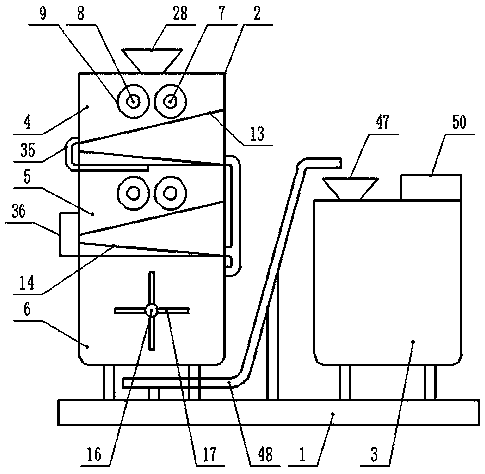
[0017] Embodiment 1: see figure 1 , figure 2 , image 3 , Figure 4 , Figure 5 , Figure 6 , a high-efficiency, energy-saving and environment-friendly calcium carbide furnace provided by the present invention is now described, including a machine base 1, the upper end of the machine base 1 is provided with a material preparation box 2 and a furnace body 3, and the material preparation box 2 is provided with a partition And the interlayer divides the inner cavity of the material preparation box 2 from top to bottom into the first grinding cavity 4, the second grinding cavity 5 and the mixing drying cavity 6, and the upper end of the first grinding cavity 4 is The first driving shaft 7 and the first driven shaft 8 are arranged in parallel at intervals on the side, and the first grinding roller sleeves are respectively set in the first grinding chamber 4 and outside the first driving shaft 7 and the first driven shaft 8. 9. A second driving shaft 10 and a second driven sha...

Embodiment 2

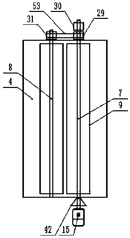
[0018] Example 2: see figure 1 , figure 2 , image 3 , Figure 4 , a high-efficiency, energy-saving and environment-friendly calcium carbide furnace provided by the present invention will now be described. Supporting columns are evenly arranged between the bottom of the material preparation box 2, the furnace body 3, and the upper end of the machine base 1. The material preparation box 2. There is a feeding opening on the middle side of the top and along its length direction. The outer top of the material preparation box 2 is provided with a feeding hopper 28 corresponding to the position of the feeding opening. The first driving shaft 7 and the first driven shaft 8, The second driving shaft 10 and the second driven shaft 11 are respectively arranged along the length direction of the first grinding chamber 4 and the inner cavity of the second grinding chamber 5, and both ends of the first driving shaft 7 in the length direction are respectively movable through The inner en...

Embodiment 3

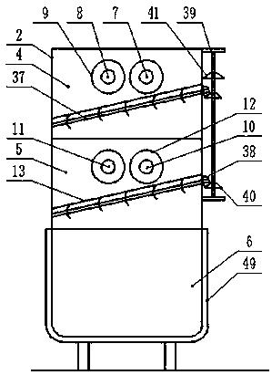
[0019] Embodiment 3: see figure 1 , figure 2 , image 3 , a high-efficiency, energy-saving and environment-friendly calcium carbide furnace provided by the present invention is now described. In the first grinding chamber 4 and the second grinding chamber 5, a rotating shaft 37 is respectively arranged below the position close to the inclined screen 13. The rotating shaft 37 is arranged in parallel with the inclined screen 13 at intervals, and the upper ends in the inclined direction of the rotating shaft 37 are respectively movable and extend through the inner end wall of the storage box 2, and the protruding ends are respectively covered with fourth Transmission gear 38, the position of the fourth transmission gear 38 is vertically provided with a transmission shaft 39, the outside of the transmission shaft 39 and the position corresponding to the fourth transmission gear 38 are respectively covered with a third transmission gear 40, the transmission shaft 39 The top is c...


PUM


Abstract

The invention discloses an efficient energy-saving environment-friendly calcium carbide furnace. The furnace comprises a machine base, a material preparation box body and a furnace body are arranged at the upper end of the machine base, the inner cavity of the material preparation box body is divided into a first grinding cavity, a second grinding cavity and a material mixing drying cavity throughpartition layers, a first driving shaft, a first driven shaft, a first grinding roller sleeve are arranged in the first grinding cavity, a second driving shaft, a second driven shaft, a second grinding roller sleeve are arranged in the second grinding cavity, inclined mesh screens are arranged at the lower end of an inner cavity of the first grinding cavity and the lower end of an inner cavity ofthe second grinding cavity correspondingly, inclined material guiding plates are arranged at the bottom end of the inner cavity of the first grinding cavity and the bottom end of the inner cavity ofthe second grinding cavity correspondingly, a first motor is arranged on the outside end wall of the first grinding cavity, a stirring shaft is arranged on the middle side of the inner cavity of the material mixing drying cavity, a stirring rod is arranged outside the stirring shaft, and a second motor is arranged on the outside end wall of the material mixing drying cavity; and the furnace body comprises an outer shell and an inner shell, wherein the inner shell is arranged in the outer shell, and a machining assembly is arranged at the top of the outer shell.

Description

technical field [0001] The invention relates to the field of calcium carbide furnaces, in particular to a high-efficiency, energy-saving and environment-friendly calcium carbide furnace. Background technique [0002] Calcium carbide is an inorganic compound and a colorless crystal. The industrial product is a gray-black block. When the calcium carbide furnace prepares calcium carbide, a large amount of high-heat waste gas will be generated. The direct discharge of high-heat waste gas will not only cause serious environmental pollution, but also cause resources (heat energy etc.), the existing calcium carbide furnace has low preparation efficiency, high efficiency, adequacy, and uniformity cannot be guaranteed. When the calcium carbide furnace is working, raw materials will inevitably adhere to the inner end wall of the furnace body, and the adhesion of raw materials Attachment will not only cause waste of resources, but also reduce the cleanliness of the equipment, which wil...

Claims


Application Information

Patent Timeline
Patent Type & Authority Applications(China)
IPC IPC(8): F26B1/00F26B17/12F26B21/00F26B25/00F26B25/04F26B25/12
CPCF26B1/005F26B17/12F26B21/001F26B25/007F26B25/04F26B25/12F26B2200/08
Inventor 丘永桂王小勇田之俊卢鑫
Owner HWASU
Why Eureka
Try Eureka