Microscope and control method thereof

A control method and microscope technology, which is applied in the field of biological microscopes, can solve the problems of investing a large number of fully automatic scanners, and achieve the effects of improving imaging accuracy, convenient debugging, and ensuring accuracy

Active Publication Date: 2020-01-14
刘杰 +1
View PDF6 Cites 3 Cited by
  • Summary
  • Abstract
  • Description
  • Claims
  • Application Information

AI Technical Summary

Problems solved by technology

[0006] However, ordinary biological microscopes are commonly used in existing deep learning processing methods, but fully digital scanning of specimens is required in deep learning, so a large number of fully automatic scanners need to be invested

Method used


Image

  • Microscope and control method thereof
  • Microscope and control method thereof
  • Microscope and control method thereof

Examples


Embodiment 2

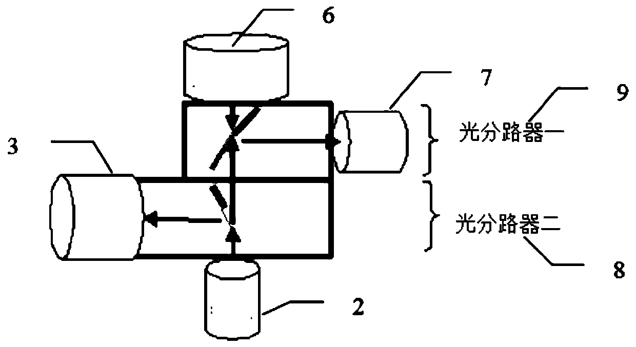
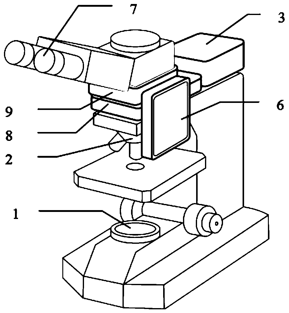
[0042] According to another embodiment of the present application, the image acquisition module 3 and the AR projection display module 6 are sequentially arranged on the first optical splitter and the second optical splitter.

[0043] An image acquisition module 3 is installed on the first optical splitter, and an AR projection display module 6 is arranged on one side of the second optical splitter. This separates image acquisition and image projection into two separate systems.

[0044] Such as image 3 As shown, according to the schematic light path shown, the microscope uses an illumination system 1 to illuminate the sample from below, and a microscope imaging module 2, such as a conventional objective lens, to capture the image light. These rays travel upward to the eye in a collimated state. An optical splitter-8 is inserted in the optical path of the collimated light space. A second optical splitter 9 is inserted between the eyepiece and the first optical splitter to ...

Embodiment 3

[0046] The microscope control method flow of the present application, such as Figure 4 shown, including the following steps:

[0047] Step S410, capturing the image of the observation body;

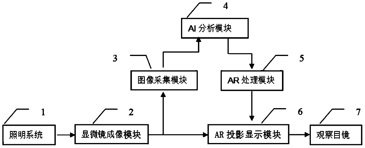
[0048] The illumination system in the microscope provides a suitable light source to generate incident light, and uses the microscopic imaging module 2 to magnify the microscopic image to form the incident light path and the outgoing light path. The image acquisition module 3 is arranged on the incident optical path of the microscopic imaging module 2, and is used for capturing images of the observed object.

[0049] The image acquisition module 3 is preferably a digital camera, which ensures that the sample is in a focused state during the process of capturing images, and furthermore, the captured images are high-resolution images.

[0050] Step S420, decoding the obtained image of the observation body, using an artificial intelligence algorithm to identify and mark the decoded image,...


PUM


Abstract

The invention discloses a microscope and a control method thereof. The method comprises the following steps of capturing an image of an observation body; decoding an obtained image of the observationbody, and identifying and marking the decoded image by using an artificial intelligence algorithm to obtain AI analysis information; decomposing a real scene and an observation body from the decoded image, constructing a three-dimensional virtual reality scene corresponding to the real scene, and carrying out image synthesis on the three-dimensional virtual reality scene and the observation body;and projecting and displaying the synthesized image in an eyepiece. In the invention, a microscopic image can be captured in real time to obtain the AI analysis information, a result image and the prompt information of AI processing are superposed with the real image, and the superposed image is projected to a field of view of a microscope through AR so that an operator can observe the microscopicimage, the AI analysis processing result and prompt information at the same time in the field of view of the microscope.

Description

technical field [0001] The invention relates to the field of biological microscopes, in particular to a microscope and a control method thereof. Background technique [0002] A microscope is an instrument that produces a magnified image of an object by physical methods. It was first invented in the late 16th century and has a history of 406 years (2001). Microscope technology is now an important part of optical instruments and has become an extremely important scientific instrument, widely used in various scientific research activities such as biology, medical treatment, chemistry, electronics, semiconductors, optical manufacturing, metallurgy, and brewing. With the maturity of technology, the microscope structure has also developed a variety of forms, structures and imaging methods, which has made a huge and outstanding contribution to the development of human beings. [0003] Medical microscopy is a cytomorphological method of examining abnormal changes in human organs, ...

Claims


Application Information

Patent Timeline
Patent Type & Authority Applications(China)
IPC IPC(8): G02B21/36
CPCG02B21/36G02B21/362G02B21/365
Inventor 刘杰杨继东张志强
Owner 刘杰
Why Eureka
Try Eureka