Reagent centrifugal system

A technology for reagents and centrifuge tubes, applied in the field of centrifuges, can solve the problem of manual work for taking and placing centrifuge tubes, and achieve the effects of reducing manual work, reducing errors, and improving efficiency

Inactive Publication Date: 2020-01-17
上海宏滩生物科技有限公司
View PDF8 Cites 5 Cited by
  • Summary
  • Abstract
  • Description
  • Claims
  • Application Information

AI Technical Summary

Problems solved by technology

[0003] At present, the existing centrifuges have been able to realize automatic or semi-automatic operation, but manual work is still required for picking and placing centrifuge tubes

Method used


Image

  • Reagent centrifugal system
  • Reagent centrifugal system
  • Reagent centrifugal system

Examples


Embodiment Construction

[0039] The present invention will be further described in detail below in conjunction with the accompanying drawings. The drawings schematically show the structure and the like of the reagent centrifugation system in simplified form.

[0040] In describing the present invention, it should be understood that the terms "upper", "lower", "front", "rear", "left", "right", "top", "bottom", "inner", " The orientation or positional relationship indicated by "outside", etc. is based on the orientation or positional relationship shown in the drawings, and is only for the convenience of describing the present invention and simplifying the description, rather than indicating or implying that the referred device or element must have a specific orientation, so as to Specific orientation configurations and operations, therefore, are not to be construed as limitations on the invention.

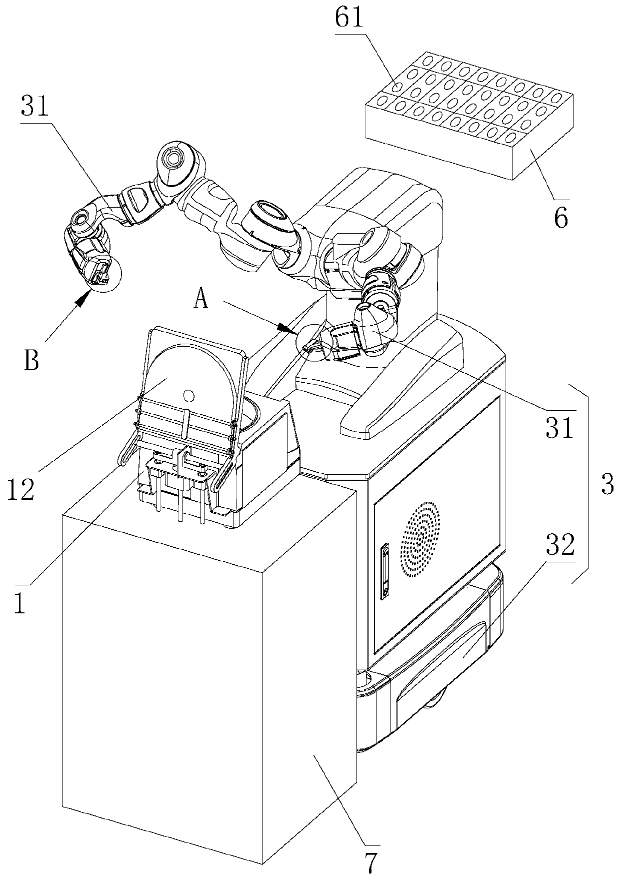
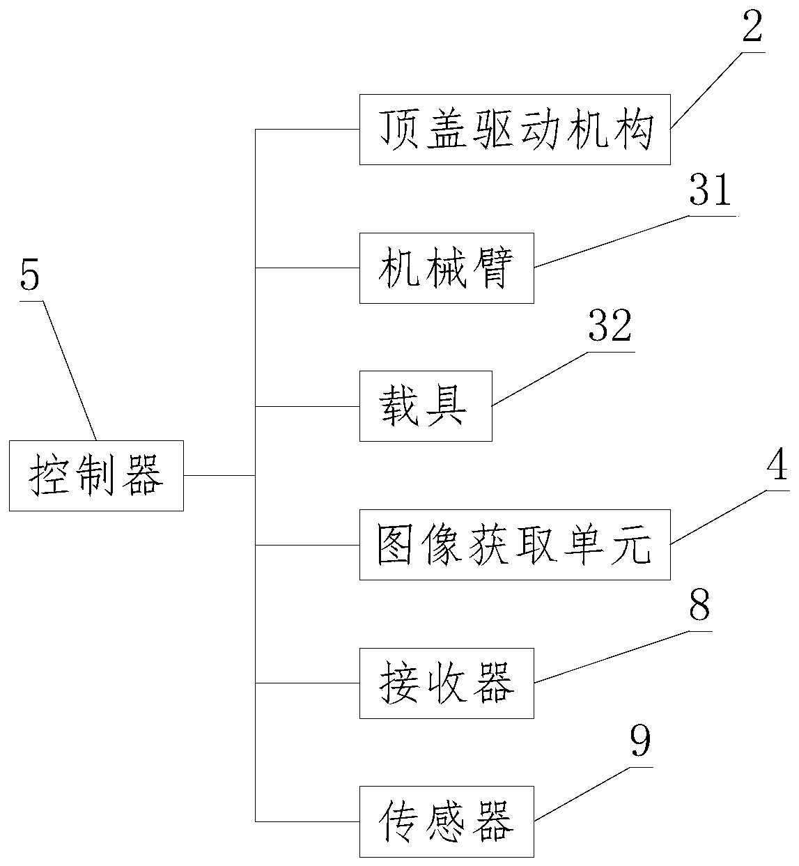
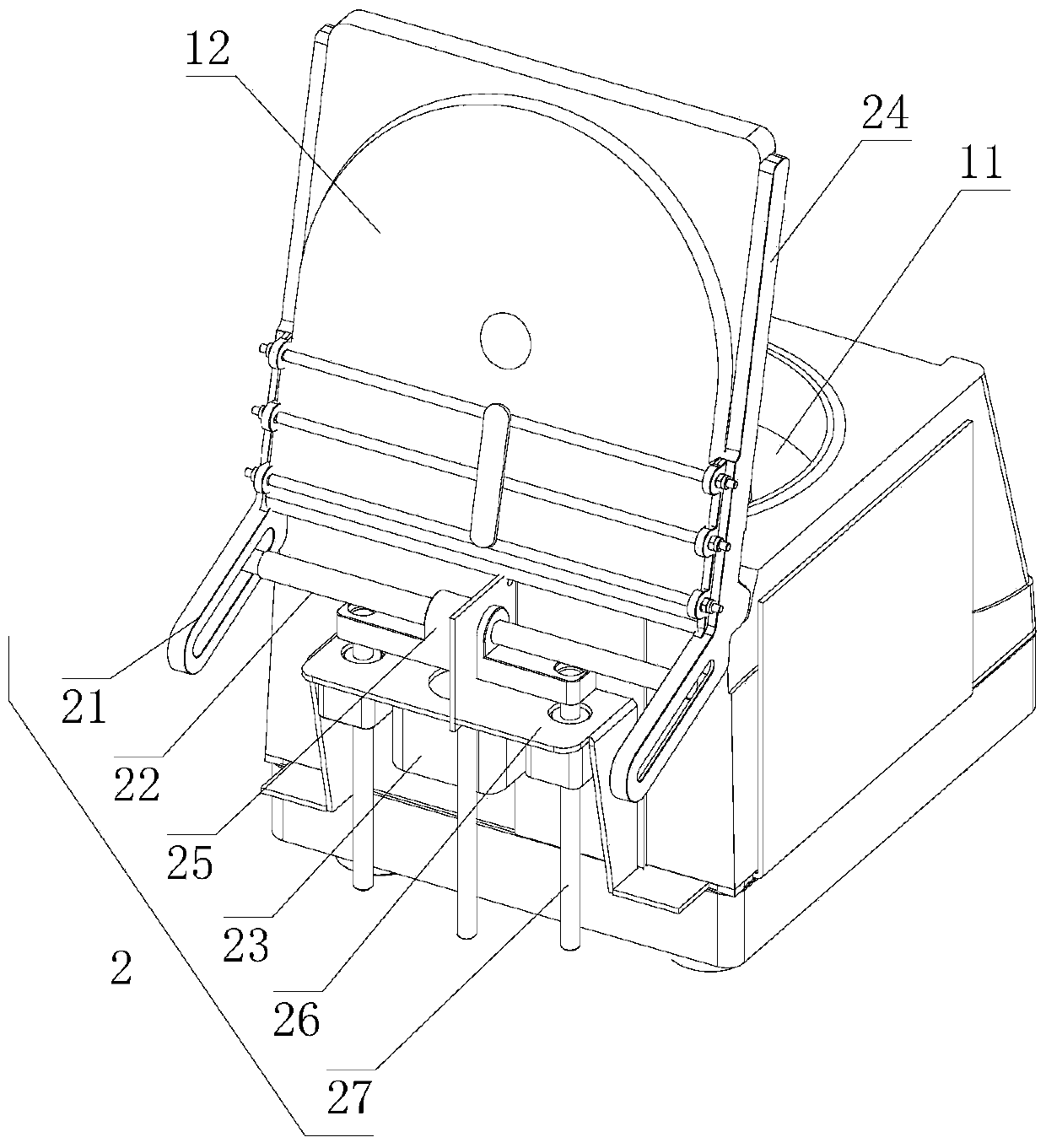
[0041] Embodiments of the present invention provide a reagent centrifugal system, see figure 1 and fi...


PUM


Abstract

The invention relates to the technical field of centrifuges and discloses a reagent centrifugal system which comprises a centrifuge, a turnover unit, an image acquisition device and a control unit; the centrifuge is provided with a top cover capable of being opened and closed and a centrifugal portion provided with a plurality of placing grooves for centrifugal tubes; the turnover unit is used incooperation with the centrifuge and is provided with a mechanical arm capable of taking and placing the centrifugal tubes; the image acquisition device can obtain an image of the centrifugal portion in the centrifuge in a state that the top cover is opened; and the control unit is in communication connection with both the image acquisition device and the mechanical arm and can control the taking and placing action of the mechanical arm by analyzing a stop position of the centrifugal portion according to the image obtained by the image acquisition device. For the reagent centrifugal system, byarranging the image acquisition device and the turnover unit and using the control unit to control the actions of the two of the image acquisition device and the turnover unit, taking, placing and position transferring of a reagent in the reagent centrifugal system can be automatically and mechanizedly achieved without manual operation, the taking, placing and position transferring efficiency of the reagent are greatly improved, and thus the centrifugal efficiency of the reagent centrifugal system is correspondingly improved.

Description

technical field [0001] The invention relates to the technical field of centrifuges, in particular to a reagent centrifugation system. Background technique [0002] A centrifuge is a machine that uses centrifugal force to separate components in a mixture of liquid and solid particles or liquid and liquid. The centrifuge is mainly used to separate the solid particles in the suspension from the liquid, or to separate two different densities and immiscible liquids in the emulsion. Centrifuges are widely used in chemical industry, petroleum, food, pharmaceutical, mineral processing, coal, water treatment and shipbuilding and other departments. [0003] At present, existing centrifuges have been able to realize automatic or semi-automatic operation, but manual work is still required for picking and placing centrifuge tubes. With the development of industrial robot technology, the demand for fully automatic biochemical testing has gradually become prominent. As the basic process...

Claims


Application Information

Patent Timeline
Patent Type & Authority Applications(China)
IPC IPC(8): B04B5/04B04B5/10B04B13/00
CPCB04B5/0414B04B5/10B04B13/00B04B2005/0435
Inventor 朱滨徐建刚邢军芬
Owner 上海宏滩生物科技有限公司
Why Eureka
Try Eureka