Lamellar nanoparticle enhanced high-temperature-resistant high-strength foam system and preparation method thereof
A nanoparticle and foam system technology, applied in the direction of chemical instruments and methods, drilling compositions, etc., can solve the problems of inapplicable heavy oil thermal recovery, etc., achieve deep control and displacement, prolong the action time, and solve the problem of short validity period Effect
- Summary
- Abstract
- Description
- Claims
- Application Information
AI Technical Summary
Problems solved by technology
Method used
Image
Examples
preparation example Construction
[0028] The present invention also relates to the preparation method of described foam system, it comprises the following steps:
[0029] (1) dispersing the flake nanoparticles in water to prepare a dispersed nanoparticle solution;
[0030] (3) Under stirring, add the high-temperature foaming agent and the interface regulator to the above-mentioned nanoparticle solution sequentially or simultaneously to obtain a foam system.
[0031] In a preferred embodiment, in step (1), the dispersion is firstly carried out by using a high-speed mixer, and then by ultrasonic dispersion.
[0032] In a preferred embodiment, in step (2), the stirring is carried out at a speed of above 8000 rpm, such as above 10000 rpm, for more than 30 seconds, such as above 60 seconds.
[0033] In a specific embodiment, the foam system is prepared as follows:
[0034] Fully disperse a certain amount of nanoparticles in water at 50-80°C, stir with a high-speed mixer at 10,000rpm for several minutes, for examp...
Embodiment 1
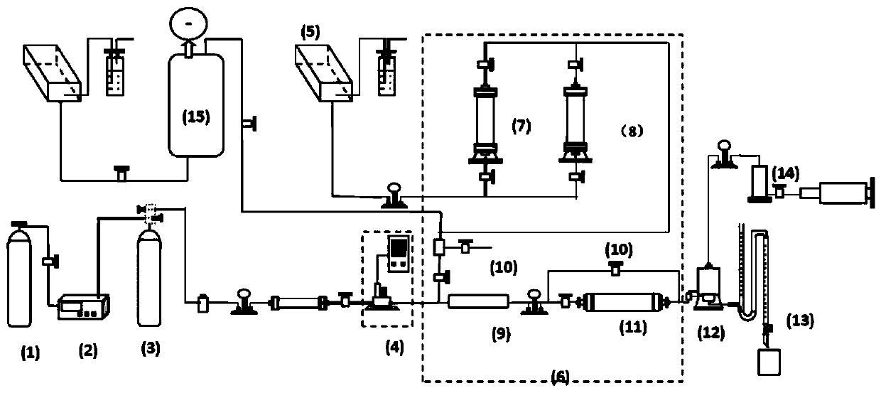
[0043] With 0.1g graphene oxide (its specific surface area 420m 2 / g) placed in 99.3g of water at 60°C to fully disperse, using a high-speed stirrer to stir at 10000rpm for 5min, and then disperse it in an ultrasonic disperser for 10min to form a nanoparticle solution. Then, 0.5 g of sodium dodecylbenzene sulfonate and 0.1 g of tetrasodium aminotrimethylene phosphonate were simultaneously added to the above nanoparticle solution, and stirred with a high-speed mixer at 10,000 rpm for 1 min to obtain a foaming liquid. Inject 20g of foaming liquid into a high-temperature and high-pressure foam apparatus. The temperature of the foam apparatus is set at 150°C and the pressure is 7MPa. Nitrogen is injected at a speed of 150ml / min. The maximum foam height is 12.5cm and the half-life of the foam is 5.2min.
Embodiment 2
[0045] With 0.05g graphene oxide (its specific surface area 420m 2 / g), 0.15g laponite (its specific surface area is 370m 2 / g) placed in 99.1g of water at 60°C to fully disperse, using a high-speed stirrer to stir at 10,000rpm for 5min, and then place it in an ultrasonic disperser for 10min to form a nanoparticle solution. Then, 0.5 g of sodium dodecylbenzenesulfonate and 0.2 g of potassium hydroxyethylidene diphosphonate were simultaneously added to the above nanoparticle solution, and stirred at 10,000 rpm for 1 min with a high-speed mixer to obtain a foaming liquid. Inject 20g of foaming liquid into a high-temperature and high-pressure foam apparatus. The temperature of the foam apparatus is set at 150°C and the pressure is 7MPa. Nitrogen is injected at a speed of 150ml / min. The maximum foam height is 12.9cm and the half-life of the foam is 5.1min.
PUM
| Property | Measurement | Unit |
|---|---|---|
| specific surface area | aaaaa | aaaaa |
| specific surface area | aaaaa | aaaaa |
| specific surface area | aaaaa | aaaaa |
Abstract
Description
Claims
Application Information
 - R&D
- Intellectual Property
- Life Sciences
- Materials
- Tech Scout
- Unparalleled Data Quality
- Higher Quality Content
- 60% Fewer Hallucinations
Browse by: Latest US Patents, China's latest patents, Technical Efficacy Thesaurus, Application Domain, Technology Topic, Popular Technical Reports.
© 2025 PatSnap. All rights reserved.Legal|Privacy policy|Modern Slavery Act Transparency Statement|Sitemap|About US| Contact US: help@patsnap.com


