
Steel alloy

A technology for steel alloys and alloys, applied in the coating process of metal materials, bearings, shafts, etc., can solve the problems of damage to the microstructure toughness of the core, damage to the toughness and crack resistance of the bearing ring, etc.

Active Publication Date: 2020-01-17
AB SKF +1
View PDF8 Cites 1 Cited by
  • Summary
  • Abstract
  • Description
  • Claims
  • Application Information

AI Technical Summary

Problems solved by technology

This is because an excess of delta-ferrite will impair the toughness of the core microstructure, thereby compromising the toughness and crack resistance of the bearing ring

Method used


Image

  • Steel alloy
  • Steel alloy
  • Steel alloy

Examples


Embodiment Construction

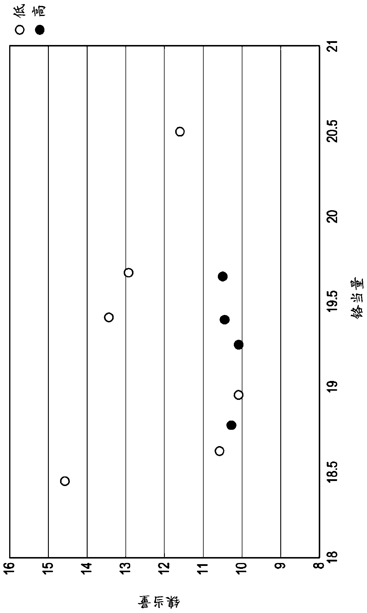
[0098] Various steel alloys having the compositions listed in Table 1 were prepared.

[0099] steel C Si mn Cr Mo Ni V Nb co Ni eq

P675* 0.07 0.40 0.65 13.0 1.8 2.6 0.6 - 5.4 10.4 A* 0.076 0.18 0.47 12.42 2.0 0.53 0.6 0.032 7.2 10.3 B2* 0.069 0.16 0.47 12.05 2.5 1.04 0.5 0.030 7.23 10.6 B3* 0.054 0.16 0.47 11.19 3.46 1.02 0.51 0.033 7.18 10.1 B4* 0.050 0.15 0.47 12.37 2.49 1.83 0.51 0.033 6.51 10.1 B5 0.09 0.18 0.18 11.3 3.5 1.8 0.5 0.05 8.8 13.4 C2 0.054 0.17 0.51 13.4 2.74 1.54 0.53 0.032 8.16 11.6 C4* 0.040 0.16 0.47 11.31 3.48 0.54 0.51 0.033 8.47 10.4 D2* 0.050 0.21 0.68 11.45 1.82 0.56 1.01 0.034 8.06 10.5 C5 0.16 0.17 0.23 11.3 3.44 0.43 0.33 0.04 9.2 14.5 C6 0.11 0.16 0.16 11.2 3.6 0.41 0.55 0.04 9.1 12.6

[0100]Table 1 - Chemical composition of various steel alloys according to the i...


PUM


Abstract

A steel alloy comprising:from 0.05 to 0.25 wt.% carbon,from 10 to 14 wt.% chromium,from 1.5 to 4 wt.% molybdenum,from 0.3 to 1.2 wt.% vanadium,from 0.3 to 3 wt.% nickel,from 6 to 11 wt.% cobaltfrom 0.05 to 0.4 wt.% silicon,from 0.1 to 1 wt.% manganese,from 0.02 to 0.06 wt.% niobium,optionally one or more of the following elementsfrom 0 to 2.5 wt.% copperfrom 0 to 0.1 wt.% aluminium,from 0 to 250 ppm nitrogen,from 0 to 30 ppm boron, andthe balance iron, together with any unavoidable impurities,wherein the alloy has a Nieqof greater than 11.5, the Nieqbeing defined by the formula Nieq= Ni + Co +(0.5 * Mn) + (30 * C), in wt.%.

Description

technical field [0001] The invention relates to the fields of steel and bearings. More specifically, the present invention relates to a novel steel alloy, method of forming bearing components, and bearings including such components. Background technique [0002] Bearings are devices that allow constrained relative motion between two components. Rolling element bearings include inner and outer raceways and a plurality of rolling elements (balls or rollers) disposed therebetween. For long-term reliability and performance, it is important that the individual components have a high resistance to rolling fatigue, wear and creep. Bearings used in aerospace applications often need to operate under high loads and extreme temperatures in environments where they may be exposed to moisture. Therefore, these parts need to have an optimal combination of toughness, high temperature performance and corrosion resistance, in addition to excellent surface hardness and core ductility. [0...

Claims


Application Information

Patent Timeline
Patent Type & Authority Applications(China)
IPC IPC(8): C22C38/44C22C38/46C22C38/52C22C38/02C22C38/04C22C38/48C22C38/42C22C38/06C22C38/54F16C33/62F16C33/30
CPCC22C38/44C22C38/46C22C38/52C22C38/02C22C38/04C22C38/48C22C38/42C22C38/06C22C38/54F16C33/62F16C33/30C21D2211/008C21D2211/001F16C2204/62F16C2204/70F16C2206/40F16C2223/12F16C2223/14F16C2223/16C23C8/20C23C8/26C23C8/32C23C8/80C21D1/06C21D9/40C21D2211/005F16C33/303
Inventor J.贝斯威克A.凯瑞甘Y.马赫奥A.蒙德林M.谢里夫
Owner AB SKF
Learn More