Constant-pressure constant-flow sludge pumping system

A technology of constant flow, sludge pump, applied in pump control, liquid variable capacity machinery, machine/engine, etc., can solve the problems of continuous operation of constant pressure and constant flow, large impact of hydraulic system, unstable pipeline pressure, etc. Improve production efficiency, stabilize furnace temperature, and stabilize exhaust gas treatment

Pending Publication Date: 2020-01-17
XUZHOU SHENGYUAN ENVIRONMENTAL TECH CO LTD
View PDF6 Cites 1 Cited by
  • Summary
  • Abstract
  • Description
  • Claims
  • Application Information

AI Technical Summary

Problems solved by technology

[0003] At present, the existing sludge pumping system cannot operate continuously at constant pressure and constant flow. During intermittent operation, the pipeline will vibrate greatly, resulting in unstable pipeline pressure and a relatively large impact on the hydraulic system.

Method used


Image

  • Constant-pressure constant-flow sludge pumping system
  • Constant-pressure constant-flow sludge pumping system

Examples


Embodiment Construction

[0014] The following will clearly and completely describe the technical solutions in the embodiments of the present invention with reference to the accompanying drawings in the embodiments of the present invention. Obviously, the described embodiments are only some, not all, embodiments of the present invention. Based on the embodiments of the present invention, all other embodiments obtained by persons of ordinary skill in the art without making creative efforts belong to the protection scope of the present invention.

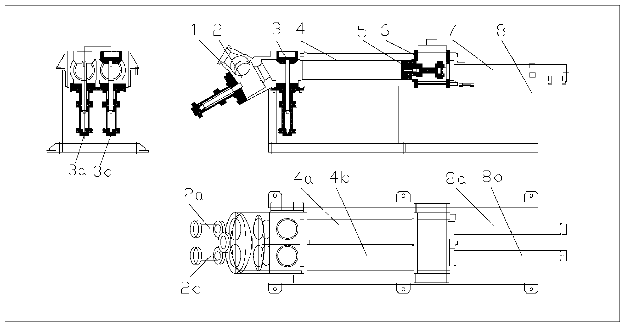
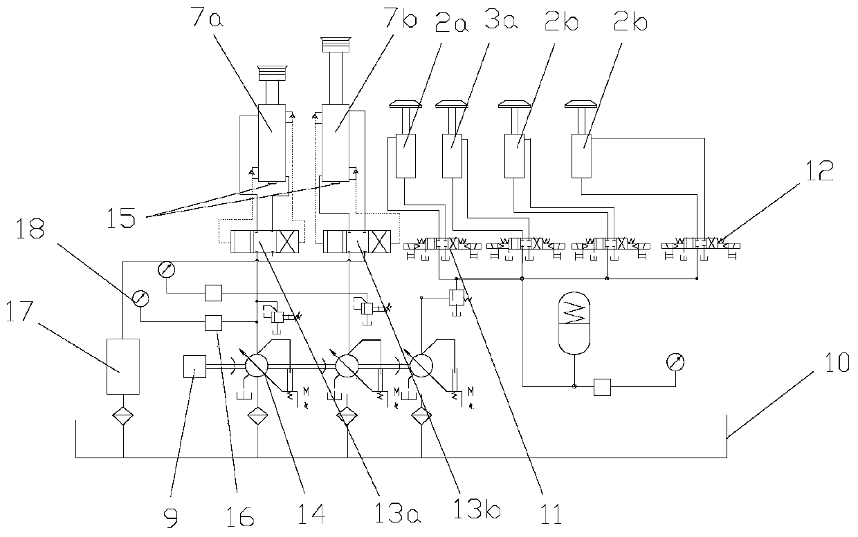
[0015] Such as Figure 1 to Figure 2 As shown, a constant pressure and constant flow sludge pumping system includes a sludge plunger pump, a hydraulic system and an electric control system; the sludge plunger pump includes a hopper 1, a discharge cone valve 2, a feed cone valve 3, Material cylinder 4, piston 5, water tank 6, main oil cylinder 7 and base 8; hydraulic system includes motor 9, three variable plunger oil pumps, oil tank 10, hydraulically controlle...


PUM


Abstract

The invention discloses a constant-pressure constant-flow sludge pumping system, relates to the technical field of sludge disposal equipment, and aims to solve the problem that an existing sludge pumping system cannot continuously convey sludge at constant pressure and constant flow. The system comprises a sludge plunger pump, a hydraulic system and an electric control system. The hydraulic systemcomprises a motor, three variable plunger oil pumps, an oil tank, a hydraulic control three-position four-way reversing valve for controlling the main oil cylinder, two first electromagnetic three-position four-way reversing valves for controlling discharge cone valves, and two second electromagnetic three-position four-way reversing valves for controlling feeding cone valves. The variable plunger oil pumps are located above the oil tank and connected with the oil tank through oil pipes. The electric control system comprises a PLC, a displacement sensor and a pressure transmitter, wherein thedisplacement sensor and the pressure transmitter are in control connection with the PLC. By means of the system, sludge can be continuously conveyed at constant pressure and constant flow, continuousproduction is achieved in the aspects of sludge carbonization and sludge thermal hydrolysis, the production efficiency is improved, the furnace temperature can be stabilized in the aspect of sludge incineration, and meanwhile, later tail gas treatment is stable.

Description

technical field [0001] The invention relates to the technical field of sludge disposal equipment, in particular to a constant pressure and constant flow sludge pumping system. Background technique [0002] The sludge pumping system is a continuous and stable transport of sludge with a water content of more than 70% at a constant pressure and constant flow rate to the lower-level equipment. It consists of a sludge plunger pump, a hydraulic power pack, and a pipeline. It is mainly used for sludge carbonization , thermal hydrolysis of sludge, waste incinerator and other sludge treatment and disposal processes. [0003] At present, the existing sludge pumping system cannot operate continuously at constant pressure and constant flow. During intermittent operation, the pipeline will vibrate greatly, resulting in unstable pipeline pressure and a relatively large impact on the hydraulic system. Contents of the invention [0004] In view of the above-mentioned technical deficienci...

Claims


Application Information

Patent Timeline
Patent Type & Authority Applications(China)
IPC IPC(8): F04B49/06F04B49/08F04B49/22
CPCF04B49/065F04B49/08F04B49/22
Inventor 袁厅
Owner XUZHOU SHENGYUAN ENVIRONMENTAL TECH CO LTD
Why Eureka
Try Eureka