Eureka AIR delivers breakthrough ideas for toughest innovation challenges, trusted by R&D personnel around the world.

Premixed carbon dioxide pneumatic laser driven by combustion of continuous rotary detonation rocket

A technology driven by combustion and carbon dioxide, which is applied to lasers, laser components, phonon exciters, etc., can solve the problems of low energy efficiency ratio, low light output rate, low laser efficiency, etc., and achieve high thermal cycle efficiency, improved laser efficiency, The effect of high laser efficiency

Active Publication Date: 2020-01-17
PLA PEOPLES LIBERATION ARMY OF CHINA STRATEGIC SUPPORT FORCE AEROSPACE ENG UNIV
View PDF13 Cites 8 Cited by
  • Summary
  • Abstract
  • Description
  • Claims
  • Application Information

AI Technical Summary

Problems solved by technology

[0008] 2. CO due to traditional rocket combustion drive 2 The laser efficiency produced by the laser is low. Therefore, when producing a laser with a set output, the amount of fuel required is large and the energy efficiency ratio is low.
Moreover, due to the low light extraction rate and no special design, the large equipment volume makes it only used for ground light extraction experiments

Method used


Image

  • Premixed carbon dioxide pneumatic laser driven by combustion of continuous rotary detonation rocket
  • Premixed carbon dioxide pneumatic laser driven by combustion of continuous rotary detonation rocket
  • Premixed carbon dioxide pneumatic laser driven by combustion of continuous rotary detonation rocket

Examples


Embodiment Construction

[0042] The present invention will be further described in detail below in conjunction with the accompanying drawings and specific preferred embodiments.

[0043] In the description of the present invention, it should be understood that the orientations or positional relationships indicated by the terms "left side", "right side", "upper", "lower" are based on the orientations or positional relationships shown in the accompanying drawings, and are only For the purpose of describing the present invention and simplifying the description, rather than indicating or implying that the device or element referred to must have a specific orientation, be constructed and operate in a specific orientation, "first", "second" and the like do not represent components importance, and therefore should not be construed as limiting the invention. The specific dimensions used in this embodiment are only for illustrating the technical solution, and do not limit the protection scope of the present in...


PUM


Abstract

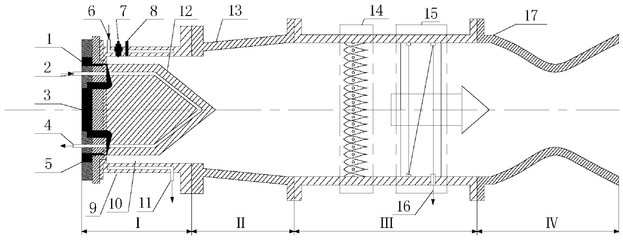
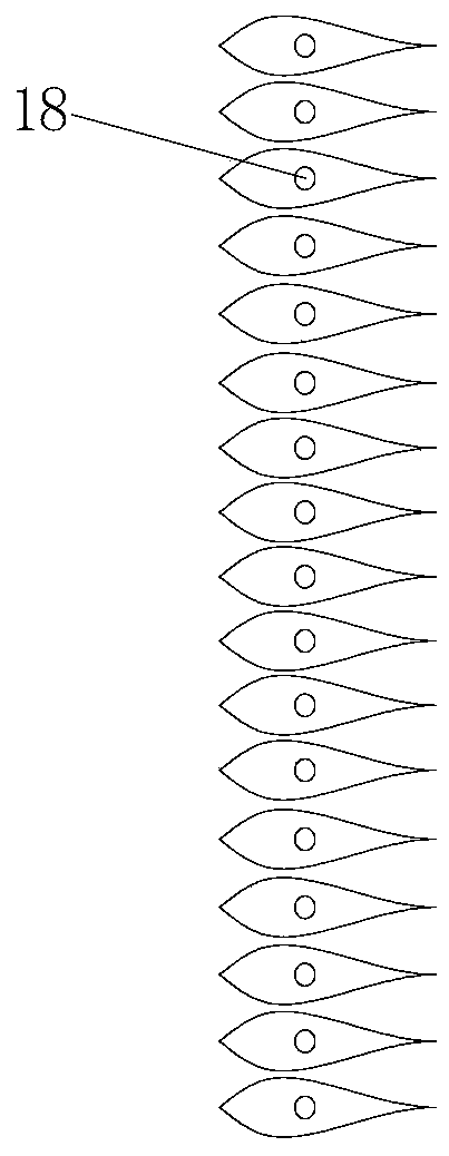
The invention discloses a premixed carbon dioxide pneumatic laser driven by the combustion of a continuous rotary detonation rocket. The premixed carbon dioxide pneumatic laser comprises a continuousrotary detonation combustion device, a transition section, a CO2 pneumatic laser generation device and an exhaust section. The continuous rotary detonation combustion device is used for generating a high-temperature and high-pressure fuel gas heat source as a total energy source of downstream output laser and comprises a shell, a central cone, a rotary detonation combustion chamber and an injection panel, the transition section enables the fuel gas behind the combustion device to adapt to configuration changes, and enables the fuel gas to stably flow to the front of an array spray pipe with the total pressure loss as small as possible, the CO2 pneumatic laser generating device comprises the array spray pipe and an optical cavity, and the exhaust section enables a product gas after light emitting to be rapidly exhausted to the outside. The continuous rotary detonation rocket combustion device is adopted as a pumping source, so that the produced laser is high in efficiency, and the energy is saved. The premixed carbon dioxide pneumatic laser can be used on a rocket or an aircraft boosted by a rocket, and not only can generate thrust, but also can generate laser without increasing theload, and can also be used as a high-power continuous intense laser light source on the ground.

Description

technical field [0001] The present invention relates to CO 2 In the field of pneumatic lasers, especially a premixed carbon dioxide pneumatic laser driven by continuous rotation detonation rocket combustion. Background technique [0002] Gas lasers are the lasers with the most types, the widest wavelength distribution area and the widest application in the laser family. Its outstanding advantages are: the wavelength distribution area of ​​the spectral lines it emits is wide, the beam quality is high and the output power is large. Compared with other lasers, gas lasers also have the advantages of high conversion efficiency, simple structure, and low cost, so they have been widely used. [0003] The basic working principle of the gas laser: the energy is released through the pump source, so that the gas particles are selectively excited to a certain high energy level, thereby forming a population flip between the low energy level and a certain low energy level, generating an...

Claims


Application Information

Patent Timeline
Patent Type & Authority Applications(China)
IPC IPC(8): H01S3/0953H01S3/223
CPCH01S3/0953H01S3/2232
Inventor 林伟聂万胜任永杰苏凌宇庄逢辰仝毅恒朱杨柱包恒钟战石天一陈朋郭康康史强罗修棋
Owner PLA PEOPLES LIBERATION ARMY OF CHINA STRATEGIC SUPPORT FORCE AEROSPACE ENG UNIV
Why Eureka
Eureka Blog
Learn More