
Process for the production of olefins using a circulating fluidized bed process

A circulating fluidized bed and olefin technology, applied in chemical instruments and methods, catalyst activation/preparation, catalysts, etc., can solve the problem of low selectivity, achieve the effects of improving selectivity, reducing equipment costs, and reducing fuel consumption

Active Publication Date: 2022-07-08
GAS CO +1
View PDF3 Cites 0 Cited by
  • Summary
  • Abstract
  • Description
  • Claims
  • Application Information

AI Technical Summary

Problems solved by technology

[0004] However, even in the process of limiting the contact time between the hydrocarbon and the catalyst, in the early stage of the reaction, the hydrocarbon reacts with the catalyst to rapidly generate by-products other than olefins, so the conversion rate of the reaction raw material is high, but the selectivity is very low.

Method used


Image

  • Process for the production of olefins using a circulating fluidized bed process
  • Process for the production of olefins using a circulating fluidized bed process
  • Process for the production of olefins using a circulating fluidized bed process

Examples


Embodiment 1

[0108] Example 1: High Velocity Fluidization Zone

[0109] A. Production of Cold Model

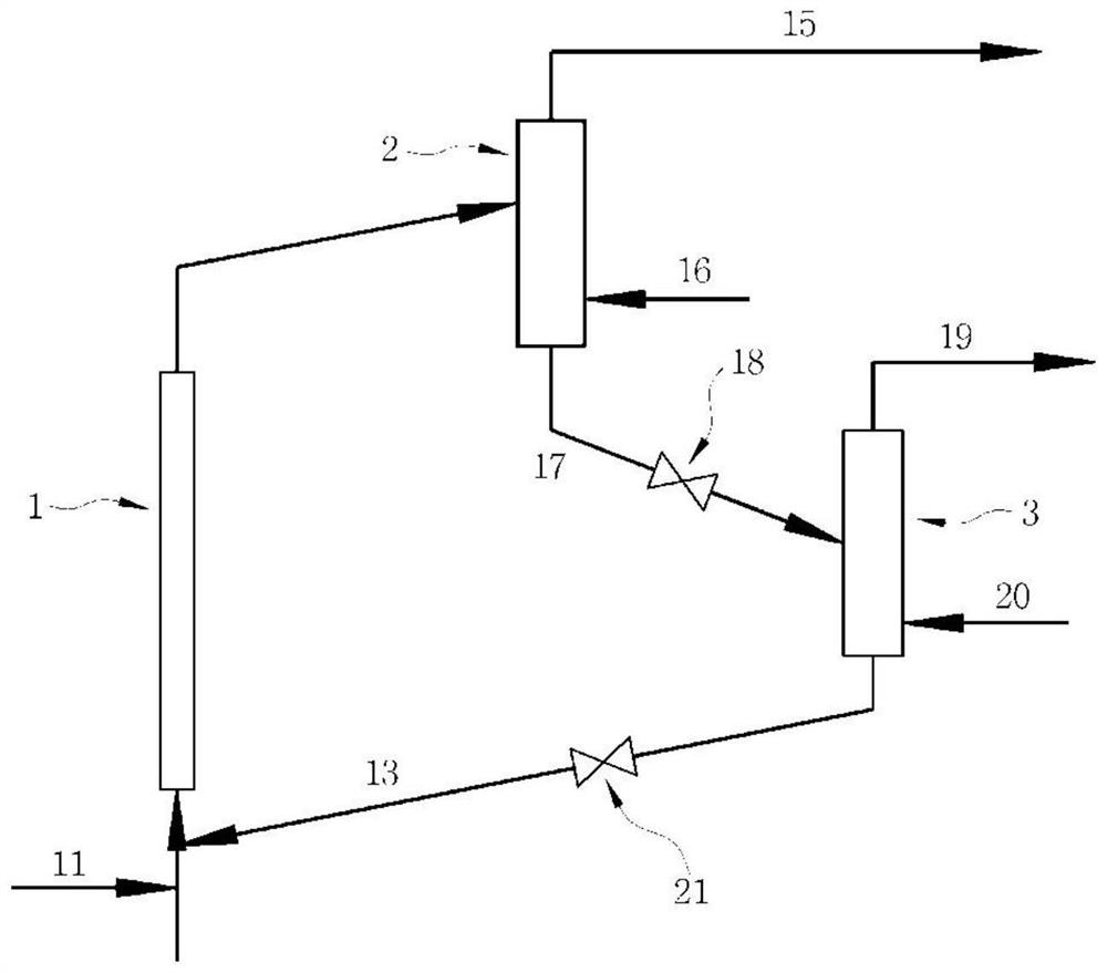
[0110] As in Comparative Example 1, such as Figure 4 made as shown.

[0111] B. Catalyst

[0112] The same catalyst as in Comparative Example 1 was used.

[0113] C. Fluidized Flow Region Experiment

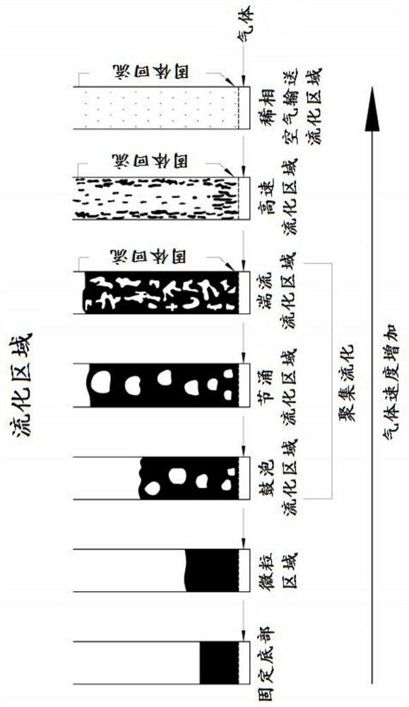
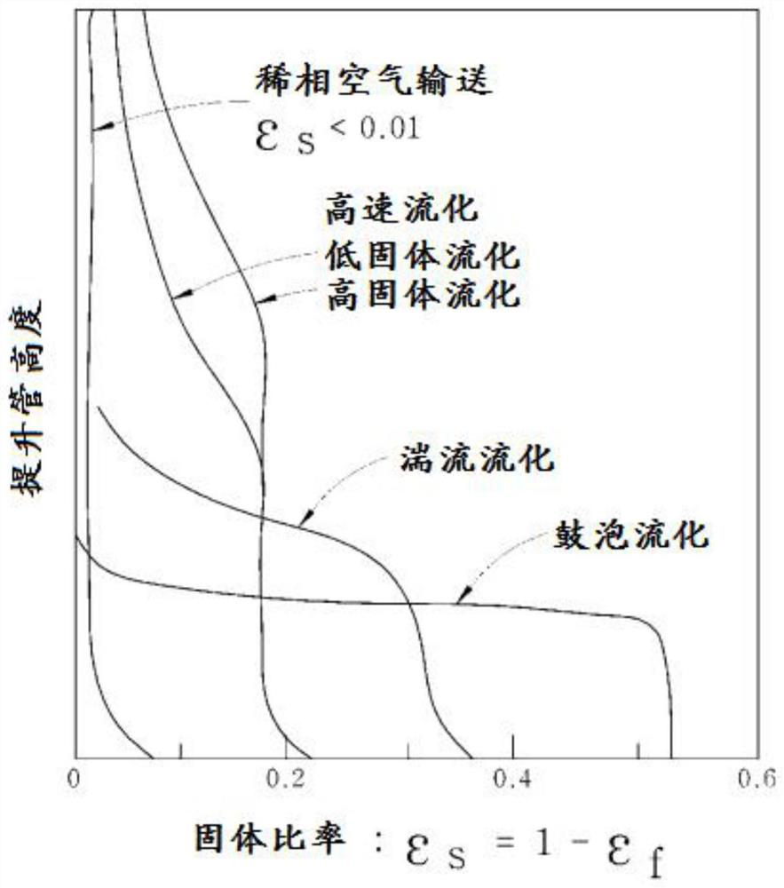
[0114] In the same manner as in Comparative Example 1, the catalyst circulation rate was injected at 7.7 kg / hr through the lower inlet of the riser, which corresponds to 33.6 kg / m2.s inside the riser. Under these conditions, according to the height of the riser, the pressure drop value was measured to obtain the solid fraction of the catalyst (cf. Image 6 ). exist Image 6 , the catalyst volume fractions at the lower 1 / 4 position and 3 / 4 position of the riser are 0.092 and 0.049, respectively, and the difference between the two positions is 0.043. According to the definition of the present invention, it can be seen that the fluidization in the high-speed fluidization region is exhibi...

Embodiment 2A

[0134] Example 2A. Catalyst Preparation

[0135] A catalyst was prepared in the same manner as in Comparative Example 2.

[0136] B. The steam treatment process of the catalyst

[0137] The catalyst was subjected to steam treatment in the same manner as in Comparative Example 2.

[0138] C. Olefin preparation process

[0139] In Example 2, the same circulating fluidized bed process as in Comparative Example 2 was used except for the riser. Here, the height of the used riser was 2.4 m and the diameter was 0.94 cm.

[0140] The raw materials used were the same as those in Comparative Example 2, and the raw materials were 300 g / hr and 590°C, and the space velocity of the catalyst was 8400 ml / gcat.hr and 640°C. On the other hand, the injection amount of the catalyst was 33.6 kg / m in consideration of the cross-sectional area of ​​the riser. 2 s (same as the cold model of Example 1).

[0141] For Example 2, the velocity of the total gas vaporized at the inlet of the riser is t...


PUM

PropertyMeasurementUnit
particle sizeaaaaaaaaaa
diameteraaaaaaaaaa

Abstract

The present invention relates to a circulating fluidized bed process for producing olefins from hydrocarbon feedstocks using a high-velocity fluidized bed, and proposes a preferred process configuration for increasing the production of olefins more efficiently. According to the present invention, by utilizing a catalyst capable of realizing dehydrogenation reaction in a circulating fluidized bed process and a high-speed fluidized region, a more sufficient volume ratio and distribution of catalyst capable of dehydrogenation reaction can be provided, and the production amount of olefins can be effectively increased , in particular, the excellent selectivity to propylene can be maintained.

Description

technical field [0001] The present invention relates to a process for the production of olefins utilizing a circulating fluidized bed process. Background technique [0002] Olefins such as ethylene and propylene are widely used in the petrochemical industry. Generally, such olefins are obtained in the pyrolysis process of naphtha. However, due to the shale gas revolution and the like, the competitiveness of processes using lower hydrocarbons as raw materials has gradually increased, and thus an on-purpose production process of olefins through a catalytic dehydrogenation process is required. [0003] The catalytic contact dehydrogenation process required for the production of olefins uses a wide variety of lower hydrocarbon compounds as feedstocks and exhibits excellent olefin production yields. However, in the fixed-bed commercial dehydrogenation process, although the olefin yield is high in the initial stage of the reaction between the hydrocarbon and the catalyst, deacti...

Claims


Application Information

Patent Timeline
Patent Type & Authority Patents(China)
IPC IPC(8): C07C5/32C07C11/06C07C9/08B01J37/06B01J35/02B01J35/00
CPCC07C2523/26C07C5/48B01J23/8872B01J23/94B01J35/40C07C11/06C07C5/322C07C9/08B01J37/06C07C2523/02C07C2521/04B01J2208/00557B01J2208/00539Y02P20/584B01J21/066B01J23/26B01J23/92B01J38/30C07C5/3332C07C2521/06
Inventor 朴德守洪雄基安亨赞崔源春朴容起
Owner GAS CO
Learn More