Supercharge Your Innovation With Domain-Expert AI Agents!

A slicing method, method, product and equipment for 3D printing

A 3D printing and slicing technology, applied in the field of additive manufacturing, can solve problems such as dead corners and too small partitions, and achieve the effect of improving surface flatness, partitioning uniformity, and reducing component cracking

Active Publication Date: 2021-07-27
TSC LASER TECH DEV BEIJING CO LTD
View PDF9 Cites 0 Cited by
  • Summary
  • Abstract
  • Description
  • Claims
  • Application Information

AI Technical Summary

Problems solved by technology

[0003] In order to solve the problems of too small partitions and dead angles when the slice layer is partitioned in the prior art, a 3D printing slicing method, method, product and equipment are provided

Method used


Image

  • A slicing method, method, product and equipment for 3D printing
  • A slicing method, method, product and equipment for 3D printing
  • A slicing method, method, product and equipment for 3D printing

Examples


Embodiment 1

[0074] A slicing method for 3D printing, comprising the following steps:

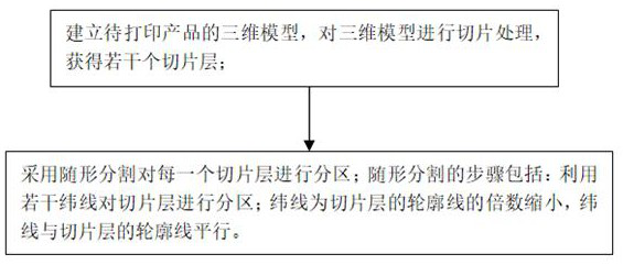
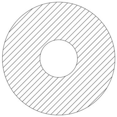
[0075] S1. Establish a three-dimensional model of the product to be printed, and slice the three-dimensional model to obtain several slice layers; the slice layers are as follows: image 3 shown.

[0076] S2. Using conformal segmentation to partition each slice layer; the step of conformal segmentation includes:

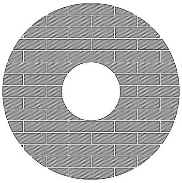
[0077] S201. Use several weft lines 1 to partition the slice layer; the weft line 1 is reduced by a multiple of the contour line of the slice layer, and the weft line 1 is parallel to the contour line of the slice layer. The spacing between any two adjacent wefts 1 is equal, and the spacing between adjacent wefts 1 is 25 mm, such as Figure 4 shown.

[0078] S202. After partitioning the slice layer by using several weft threads 1, partition the slice layer again by using several warp threads 2, where the warp thread 2 is the normal line of the latitude thread 1, and the warp thread 2 inters...

Embodiment 2

[0084] The 3D printing slicing method of this embodiment is basically the same as that of Embodiment 1, except that the distance between adjacent latitude lines 1 is 40 mm, and the length of sub-line segments is 200 mm. Then use weft 1 to partition, that is, step S202 is executed first, and then step S201 is executed.

[0085] Observation of the metal components of this embodiment shows that the surface is smooth and free of cracks.

Embodiment 3

[0087] The 3D printing slicing method of this embodiment is basically the same as that of Embodiment 1, except that the distance between adjacent parallel lines 1 is 32 mm, and the length of sub-lines is 170 mm.

[0088] Observation of the metal components of this embodiment shows that the surface is smooth and free of cracks.


PUM

PropertyMeasurementUnit
Widthaaaaaaaaaa

Abstract

The invention relates to the technical field of additive manufacturing, and specifically discloses a 3D printing slicing method, comprising the following steps: establishing a three-dimensional model of a product to be printed, performing slicing processing on the three-dimensional model, and obtaining several slicing layers; Each slice layer is partitioned; the step of conformal segmentation includes: partitioning the slice layer with several latitude lines; the latitude line is a multiple reduction of the contour line of the slice layer, and the latitude line is parallel to the contour line of the slice layer. The invention also discloses a 3D printing method using the slicing method, a 3D printed product and a 3D printed device. The invention can make the division of the slice layer more uniform, and improve the surface flatness and molding quality of the molding component.

Description

technical field [0001] The invention relates to the technical field of additive manufacturing, in particular to a 3D printing slicing method, method, product and equipment. Background technique [0002] In the process of 3D printing, three-dimensional modeling and slicing of products are necessary steps to formulate a 3D printing manufacturing plan. At present, the most commonly used method for partitioning the slice layer is the chessboard or grid partition method, but for parts with complex shapes , using a checkerboard or grid format for segmentation, which is prone to problems of too small partitions and dead ends near the edge of the slice layer. The grid format segmentation effect is as follows figure 1 As shown, it leads to the problems of excessive energy concentration and uneven energy distribution during the laser deposition printing process, which affects the overall performance of the product. Contents of the invention [0003] In order to solve the problems o...

Claims


Application Information

Patent Timeline
IPC IPC(8): B22F3/105B33Y50/00
CPCB33Y50/00B22F10/00B22F10/36B22F10/366B22F10/25B22F10/80Y02P10/25
Inventor 李澄董建新高佩宝崔照雯
Owner TSC LASER TECH DEV BEIJING CO LTD
Features
  • R&D
  • Intellectual Property
  • Life Sciences
  • Materials
  • Tech Scout
  • Unparalleled Data Quality
  • Higher Quality Content
  • 60% Fewer Hallucinations
Learn More