Method and apparatus for producing and storing flowable slush, particularly for ice pigging
A technology of slurry and equipment, applied in the direction of cleaning methods and utensils, lighting and heating equipment, chemical instruments and methods, etc., can solve problems such as difficulties
Active Publication Date: 2020-01-31
SUEZ GRP
5 Cites 0 Cited by
AI-Extracted Technical Summary
Problems solved by technology
[0011] However, "attempting to predict the full behavior of a giv...
Method used
[0030] The flowable slurry 2 is delivered from the outlet 16 through the supply pipe 21 to the storage tank 22, where the flowable slurry 2 is stored until required for use. A driven agitator 23 is provided for agitating the flowable slurry in the tank, the agitator 23 comprising one or more agitator elements (typically rotating blades) 24 rotated by one or more motors 25 drive. The control system 100 is arranged to control and supply power to the motor 25 of the agitator 23 so that the agitator element 24 rotates at a constant or variable speed, either continuously or intermittently, not only reflecting the The power and reflect the quality and viscosity of the slurry in the tank. Increased mass or viscosity will exert a greater torque reaction and thus reduce the stirrer speed or increase the power consumption of the motor. Slurry generation may be stopped, for example, when a target volume of liquid has been delivered to the slurry generator 10 , or when a target mass of slurry is present in the storage tank 22 as measured, for example, by the load cell 26 of the support tank 22 .
[0035] Surprisingly, even in this simple embodiment, the quality of the slurry stored in the tank without recovery after a period of storage is still acceptable for many practical ice pigging scenarios of. By performing treatment cycles less frequently and in response to actual conditions of ...
Abstract
An apparatus for generating and storing in a tank (22) a flowable slush (2) of frozen particles usable inter alia in ice pigging comprises a control system (100) which is arranged to monitor an operating parameter OP of an agitator (23) in the storage tank. The control system initiates a slush comminution and separation or dewatering cycle when a control parameter CP based on the operating parameter OP reaches a threshold value CPt. The control parameter may represent a cumulative energy input to the storage tank (22). Comminution may be performed prior to separation, with the treatment cyclebeing terminated when a sensed rheometric parameter RP of the slush circulating in the treatment flowpath reaches a target value RPt.
Application Domain
Lighting and heating apparatusIce production +3
Technology Topic
Process engineeringControl parameters +7
Image
Examples
- Experimental program(1)
Example Embodiment
[0025] Reference numerals appearing in more than one figure indicate like or corresponding parts in each of those figures.
[0026] In this specification, the solid fraction is considered to be the proportion of solid particles to the total volume of the slurry when measured by calorimetry. A simple approximation of the solid fraction can be obtained by the coffee pot method. Both methods are well known in the art and described eg in Ainslie (2010).
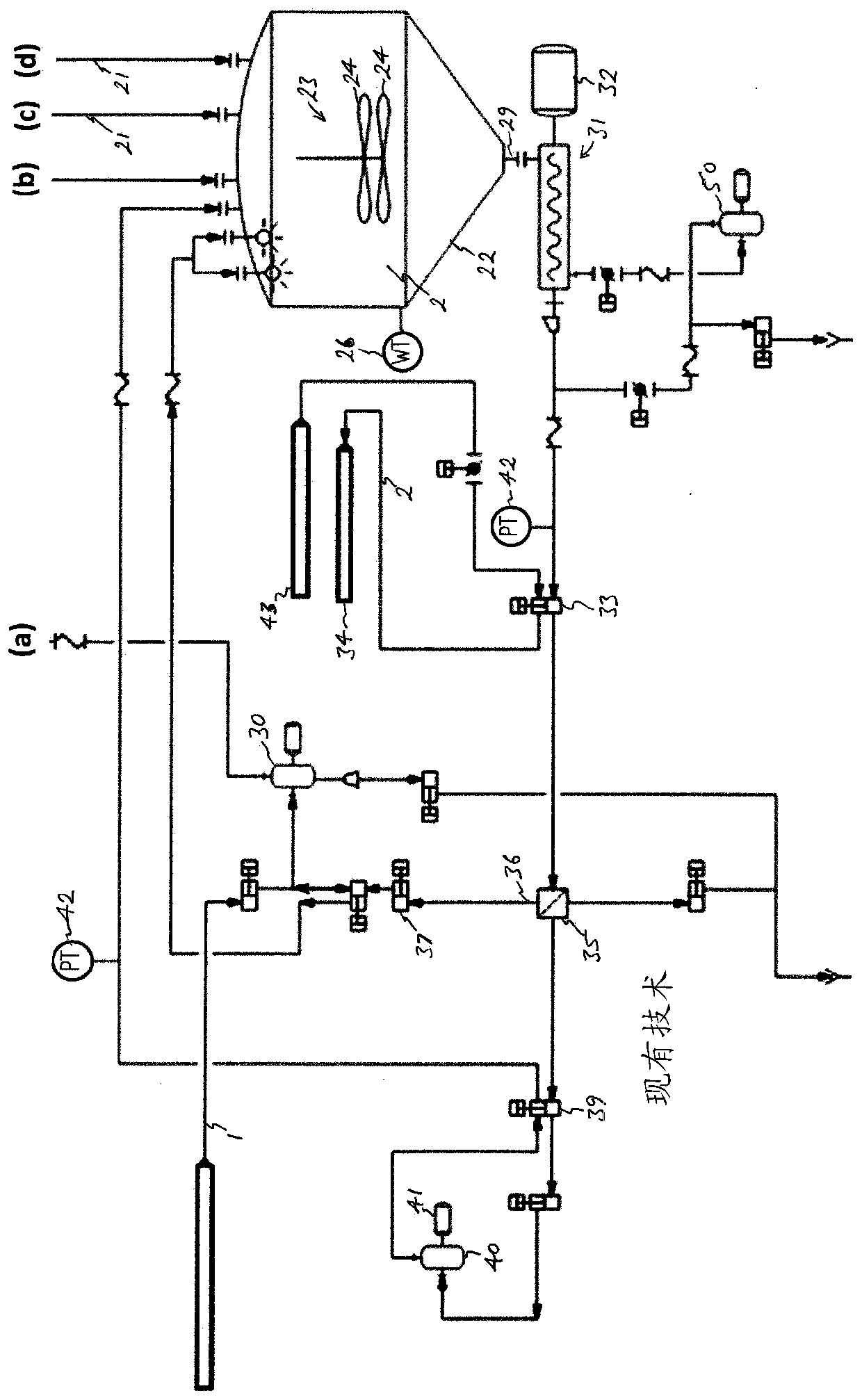
[0027] refer to image 3 , shows in simplified form an apparatus for producing a flowable slurry of frozen particles, the liquid flow paths are shown in solid lines and the slurry flow paths are shown in thick solid lines. The apparatus includes a control system 100 comprising processing and storage means known in the art, a selected one of signal and control inputs and outputs being indicated by dotted lines. For clarity, only some of the flow channels and signal or control lines are shown. Of course, it will be understood that in practice additional flow channels, valves, sensors and other functional elements will be provided, all sensing or controllable functional elements (whether in image 3 not shown in ) will be connected to the control system.
[0028] The apparatus comprises a slurry generator 10 having cooling means 11 for partially freezing the liquid 1 (ie freezing some of the liquid) to form a flowable slurry 2 . Cooling device 11 may include figure 1 A scraped surface heat exchanger of the type shown in , having a heat exchanger jacket or coil 12 that supports a coolant 13 (such as brine or refrigerant vapor ) and surrounds a substantially vertical chamber 14 having an inlet 15 for water or other liquid 1 to be frozen and an outlet 16 for removing water from the chamber by a helical screw or drill 17 The wall scrapes the slurry 2 of liquid and solid particles, while the helical screw or drill 17 is rotationally driven by a motor 18 . Liquid 1 is supplied to the inlet 15 from a tank 19 which maintains a constant water head in the cavity. Conveniently, it has been found that the drill 17 will exert a pumping action on the slurry which is proportional to the rotational speed of the drill 17 and the solids fraction of the slurry so that by controlling the rotational speed of the drill the slurry with the desired solids fraction will flow from the outlet 16 delivery.
[0029] When used to produce water ice slurry, water 3 and additives 4 including freezing point depressants at known concentrations are mixed in a defined ratio and supplied to the slurry generator 10 by a liquid supply pump 30 . When used in ice pigging, it is preferred that the slurry has a solids fraction of at least 40%, preferably at least 50%. In a particularly preferred embodiment, the rotational speed of the drill is controlled by the control system 100 based on input from a liquid supply temperature sensor ( image 3 not shown; Figure 2B The input of 51) is controlled using a control algorithm to achieve a solid fraction of approximately 55%.
[0030]The flowable slurry 2 is delivered from the outlet 16 through the supply pipe 21 to the storage tank 22, where the flowable slurry 2 is stored until required for use. A driven agitator 23 is provided for agitating the flowable slurry in the tank, the agitator 23 comprising one or more agitator elements (typically rotating blades) 24 rotated by one or more motors 25 drive. The control system 100 is arranged to control and supply power to the motor 25 of the agitator 23 so that the agitator element 24 rotates at a constant or variable speed, either continuously or intermittently, not only reflecting the The power and reflect the quality and viscosity of the slurry in the tank. Increased mass or viscosity will exert a greater torque reaction and thus reduce the stirrer speed or increase the power consumption of the motor. Slurry generation may be stopped, for example, when a target volume of liquid has been delivered to the slurry generator 10 , or when a target mass of slurry is present in the storage tank 22 as measured, for example, by the load cell 26 of the support tank 22 .
[0031] The control system comprises means for sensing at least one operating parameter OP of the agitator, which may be, for example, power consumption and/or speed of the agitator motor 25, and/or when the agitator element 24 is rotated by the motor. The torque of element 24 reacts. In either case, it will be appreciated that the operating parameter OP represents the power input to the agitator. If sensed during the reference time period, the operating parameter OP thus represents the cumulative energy input to the agitator and thus to the slurry 2 stored in the tank during the reference time period. Suitable sensing means are well known in the art and may include, for example, a motor controller or power monitoring circuit or a converter responsive to agitator shaft torque.
[0032] The control system is configured to monitor the control parameter CP, and to initiate a process cycle at least in response to the control parameter reaching a threshold CPt. The threshold CPt may be fixed or variable, and may be determined empirically or calculated through system parameters, and may be stored in the memory of the control system 100 . Therefore, in normal operation, the processing loop is not executed until the control parameter CP reaches the threshold value CPt. (Of course, the control system may be configured to provide an alternative mode of operation in which a processing cycle may optionally be executed in response to another start signal, eg, from a timer or manual control.)
[0033] The control parameter CP is based at least on the sensed operating parameter OP of the agitator. The control parameter CP may simply be the operating parameter OP, or may be algorithmically generated based on the operating parameter OP optionally together with other inputs such as the volume or mass of the slurry stored in the tank (e.g. as by weighing sensor 26), motor speed or supply voltage, etc.
[0034] In a simple embodiment, the threshold CPt may be a threshold power input or torque reaction of the stirrer, either as an instantaneous value or as an average value over a defined period of time measured eg in seconds or minutes. In this case, when the power input or torque reaction reaches a threshold, the increased load on the agitator reflects an increase in the viscosity of the slurry stored in the tank, and the process cycle can be initiated.
[0035] Surprisingly, even in this simple embodiment, the quality of the slurry stored in the tank without recovery after a period of storage remains acceptable for many practical ice pigging scenarios. By performing treatment cycles less frequently and in response to actual conditions of the slurry (especially reflecting ambient temperature and other unpredictable parameters of a particular use case), the total energy input to the stored slurry over a period of time is reduced such that Slurry generation and storage processes become more energy efficient.
[0036] However, the viscosity of the stored slurry will not only reflect melting but also other processes such as crystal growth and coagulation that occur concurrently with melting. Furthermore, depending only in part on the agitator and tank design, the slurry stored in the tank may not be homogeneous but may form one or more discrete bodies which interact more or less unpredictably with the agitator interaction. Thus, the instantaneous torque reaction of the agitator element 24 may be complex or somewhat weakly related to the mass of the slurry stored in the tank.
[0037] It was surprisingly found that there is a relatively stronger correlation between slurry quality and the cumulative energy input to the tank such that by responding to the energy input to The quality of the slurry delivered from the tank may advantageously be maintained within narrower limits by starting the process cycle with the measured cumulative energy of the tank.
[0038] In this case, the control parameter CP is calculated as an accumulated value over the reference time period, representing the accumulated energy input to the stored slurry during the reference time period. The operating parameter OP of the agitator (whether measured as torque reaction, motor armature current, and/or another parameter or group of related parameters) will represent the power input to the agitator, and thus when measured over a certain period of time represent Energy input to the mixer.
[0039] The control parameters are based on a sensed operating parameter of the agitator, optionally in combination with one or more additional parameters, during the reference time period. It is particularly preferred to base the control parameter CP on a combination of the operating parameter OP of the agitator and the temperature difference ΔT between the first temperature T1 of the liquid 1 or flowable slurry 2 and the ambient temperature T2 outside the tank. The first temperature T1 may be measured by the first temperature sensor 27 at any convenient point, for example in the flow channel or (as shown) in the tank 22 . The ambient temperature T2 may be measured by a second temperature sensor 28 external to the storage tank 22 .
[0040] In practice, the temperature difference can also be calculated based on the heat transfer coefficient U, optionally in combination with the volume or mass of the stored slurry, as determined by analysis of experimental data reflecting the geometry, capacity and other parameters of the storage tank 22. The characteristic, volume or mass of the stored slurry may be indicated by the output of the load cell 26 . refer to Figure 4 , the control parameter CP can be reset to zero at the beginning of the reference time period (step 60), and then recalculated iteratively at step 61 by increasing its initial value in successive time increments until a threshold CPt is reached, which is denoted as The comminution phase at the beginning of the processing cycle (step 62 ) ends the reference time period. Each increment of CP can be calculated using the simplified formula shown below, where AE is the agitator energy input during the corresponding time increment based on the sensed operating parameter OP:
[0041] CP=AE+U(T2-T1)
[0042] The equipment may comprise at least one slurry pump 31, conveniently a screw pump driven by a motor 32 as shown, the screw pump pumps the stored slurry from the outlet 29 of the tank to a valve 33 controlled by the control system 100 controls to direct the slurry 2 to the final outlet 34, which may be connected to external piping to be cleaned, or to circulate the slurry 2 through the process flow path and back into the tank. After discharging the slurry from the final outlet 34, the valve 33 may be configured to deliver a high volume flow of Liquid 1 from the inlet 43 to the final outlet 34 to force the slurry through the pipeline for pigging.
[0043] The process flow path passes through a separator 35 which may be formed as a perforated tube enclosed within a housing with a liquid outlet 36 . In use, pressure applied by the slurry pump 31 forces the liquid 1 out of the slurry 2 through the perforated tube into the housing. Valve 37 is operable by control system 100 to selectively connect outlet 36 to liquid pump 30 which delivers separated liquid 1 through a separate liquid valve (Vsl) 38 to slurry generator 10 for refreezing and back Tank 22, but of course the liquid 1 can be drained and discarded if desired.
[0044] Valve 39 is operable by control system 100 to selectively direct the slurry flowing through the perforated tube of separator 35 directly back into tank 22, or direct the slurry flowing through the perforated tube of separator 35 back into the tank through comminuting device 40, The pulverizing device 40 may comprise a high shear pump driven by a motor 41 which is also controlled by the control system 100 .
[0045] The slurry 2 stored in the tank 22 is processed by circulating the slurry 2 stored in the tank 22 through each of the separator 35 and the pulverizing device 40 and back into the tank 22 by the slurry pump 31 during the treatment cycle. The separator separates a portion of the liquid 1 held in the slurry 2 from the frozen particles in the separation (eg, dehydration) stage, while the pulverizer pulverizes the frozen particles to obtain a target particle size (eg, about 3 mm) in the pulverization stage.
[0046] The circulation through the separator and comminuting device can be done simultaneously or sequentially while passing through the flow channels individually, so that the separation phase and the comminuting phase occur simultaneously.
[0047] Preferably, however, the control system is arranged to start the treatment cycle with the comminution phase, that is to say the comminution phase starts before the separation phase and preferably ends before the separation phase begins. Further preferably, most or substantially all of the slurry stored in storage tank 22 is treated at step 62 ( Figure 4 ) through the comminution device 40 and back into the tank to complete the comminution phase before starting the separation phase at step 63.
[0048] Further preferably, the control system is arranged to sense a rheological parameter RP of the slurry to initiate the separation phase 63 after the comminuting phase 62, and to end the separation phase at least in response to the sensed rheological parameter RP reaching a threshold RPt at step 66 and The processing loop is thus ended.
[0049] In this specification, the rheological parameter RP is a parameter indicative of the flow characteristics of the slurry 2 .
[0050] When a slurry 2 is generated from a liquid 1 containing a known freezing point depressant at a precisely predetermined concentration, the solids portion of the slurry will be proportional to its temperature and thus can be calculated by sensing the temperature of the slurry. However, in the case of water-ice slurries with a solid fraction of 50% or greater, a temperature change of 1°C would correspond to a change in the solid fraction of approximately 12% when salt is used as a freezing point depressant, or for less effective With freezing point depressants such as sugar or citric acid, a temperature change of 1 °C will correspond to a change of up to 30% in the solids fraction. Therefore, the calculated solid fraction is highly sensitive to inaccuracies in temperature measurements.
[0051] It is also known to estimate the solids fraction by measuring the power consumption or torque reaction of agitators in storage tanks. However, as discussed above with reference to the control parameter CP, the interaction between the slurry and the agitator may not provide a reliable indication of the slurry flow characteristics.
[0052] In contrast, it was found that when the slurry is circulated through the flow channel, the flow resistance as measured, for example, by the torque or power consumption of the slurry pump or the pressure drop over a defined portion of the flow channel will reflect the particle size and solids fraction, but not the temperature of the slurry. Or chemically insensitive. Therefore, it is preferred to pump the slurry out of the storage tank, through the flow channel and back into the tank and measure the rheological parameter RP as the slurry flows through the flow channel.
[0053] Therefore, preferably, a rheological sensing device is arranged in the flow channel of the flowable slurry to sense a rheological parameter RP of the flowable slurry circulating through the flow channel during a treatment cycle.
[0054] In the example shown, the rheological sensing means includes a pressure sensor 42 that is used when the slurry pump 31 is rotating at a constant speed or when the control system senses the torque and/or speed of its motor 32 and/or inputs to its motor 32 When the power is high, the pressure sensor 42 senses the rheological parameter RP as the pressure of the flowable slurry 2 in the flow channel. Sensing is conveniently performed when the slurry is circulated through the flow channel during the separation phase, but sensing may be performed during the comminution phase, in a separate sensing phase or even through a separate flow channel. In alternative arrangements, the rheological parameter RP may be based on, for example, the torque of the slurry pump motor 32 or the power input to the slurry pump motor 32, or on the pressure between two pressure transducers spaced along a predetermined portion of the flow path. drop.
[0055] In the illustrated embodiment, the control system includes a PID controller 101 that adjusts a separate liquid valve (Vsl) 38 to control the separator 35 in response to sensed motor torque or power input to the slurry pump 31 The pressure of the separated liquid in the housing and thus controls the rate at which liquid 1 is extracted from the slurry 2 flowing through its perforated tube.
[0056]refer again Figure 4 , the separate liquid valve (Vsl) 38 is also operated by the control system to control the flow of liquid 1 from the separator 35 by periodically closing the separate liquid valve (Vsl) 38 at step 64 during the treatment cycle to control the A separate part of the device for the flow of liquid 1. When the separate liquid valve (Vsl) 38 is closed, the pressure at the sensor 42 is sensed at step 65 as the rheological parameter RP so that the pressure drop at the separator does not affect the measurement of the rheological parameter RP. Of course, another valve such as valve 37 may alternatively be used for this purpose.
[0057] Of course, it will be understood that the flow resistance of a slurry reflects, inter alia, its solids fraction and its particle size. Furthermore, the pulverization stage represents an energy input and thus accelerates melting. Thus, advantageously, by measuring the rheological parameter RP after completion of the pulverization phase, the rheological parameter RP provides an indication of the solid fraction at the target particle size, so that when the threshold RPt is reached, the process cycle can be ended without further melting .
[0058] The method provides accurate and reproducible measurements of rheological parameters that reliably indicate the quality of the slurry used, especially slurries with a solid fraction of 50% or more, where the quality of the slurry depends critically on Its solid fraction and particle size, eg when the slurry is used for ice pigging of pipelines, the quality of the slurry acts as a key determinant of wall shear. However, by relying on aggressive pumping cycles to measure the rheological parameter RP, the method necessarily requires energy input from the slurry pump to perform the measurement, thus speeding up the melting process. For this reason, the method can be considered to be less energy efficient than more passive methods, eg deriving the rheological parameter RP from agitator torque or power input.
[0059] However, by delaying the start of the treatment cycle (and thus the start of the pumping cycle, during which the rheological parameter RP is measured) until the control parameter threshold CPt is reached, the frequency of the treatment cycle and thus the net energy input of the treatment cycle is minimized . In its preferred embodiment, the novel approach thus represents a net increase in overall energy efficiency, despite incurring energy costs when compared to more passive storage systems.
[0060] now refer to Figure 2A and Figure 2B , known slurry generation and storage apparatus may be adapted to be operated by a control system (not shown) generally as described above, wherein like elements are indicated by like reference numerals. In the example shown there is a double agitator element 24 and two slurry generators 10 arranged in parallel, together with a cleaning pump 50 to facilitate pipe cleaning, auxiliary flow channels and additional valves, as well as additional functional elements Such as liquid level sensor 52 . For ease of illustration, the system is shown in two parts, which are connected together as shown at (a), (b), (c) and (d). It will be appreciated that other functional elements of the system described above may also be present, although not in Figure 2A and Figure 2B shown in .
[0061] In summary, the embodiments provide an apparatus for generating and storing in a tank a flowable slurry of frozen particles particularly useful for ice pigging. The control system is arranged to monitor operating parameters of the agitator in the storage tank, and when a control parameter based on the operating parameters reaches a threshold, the control system initiates a slurry comminution and separation or dewatering cycle. The control parameter may represent the cumulative energy input to the tank. Comminution may be performed prior to separation, with the process cycle ending when a sensed rheological parameter of the slurry circulating in the process channel reaches a target value.
[0062] In an alternative embodiment, the slurry pump may be arranged to apply shear to the slurry such that the slurry pump acts as a comminution device. However, it is preferred to provide a dedicated comminution mechanism such as a high shear pump as shown, along with a slurry pump optimized for its primary function of moving slurry through the flow channel. The pressure induced by the slurry pump advantageously facilitates efficient liquid separation and accurate measurement of sensed rheological parameters.
[0063] In an alternative embodiment comminution and separation may occur sequentially in a single operation, in which case the comminution means may be arranged in the flow channel, ahead of the separator. Alternatively, the comminution and separation stages can be performed independently or simultaneously as a parallel process, optionally using separate slurry pumps and separate flow channels. Alternatively, one or both of the pulverization process and the separation process may be performed in the storage tank.
[0064] The cooling means may comprise any suitable arrangement as known in the art for extracting heat from the liquid 1, whether by vapor compression or other refrigeration cycle, by direct or indirect contact with a liquid or gaseous refrigerant, or in any other manner . The comminuting means need not be a pump but may comprise any functional arrangement as known in the art for reducing the size of frozen particles in the slurry, whether by grinding or other direct mechanical action or otherwise. The sensing means may comprise any converter or other device for providing an output indicative of a value of a parameter of interest, whether it forms part of another device such as a motor controller or power supply arrangement or as a separate device.
[0065] Optionally, the processing loop may start in response to further parameters than the threshold CPt. For example, it may be preferable to set a minimum period of time that must elapse between successive processing cycles, in which case the processing cycle may also depend on a timer input.
[0066] Many further possible modifications within the scope of the claims will be apparent to a person skilled in the art.
[0067] In the claims, reference characters and reference signs are provided in parentheses for ease of understanding and should not be construed as limiting the features.
PUM


Description & Claims & Application Information
We can also present the details of the Description, Claims and Application information to help users get a comprehensive understanding of the technical details of the patent, such as background art, summary of invention, brief description of drawings, description of embodiments, and other original content. On the other hand, users can also determine the specific scope of protection of the technology through the list of claims; as well as understand the changes in the life cycle of the technology with the presentation of the patent timeline. Login to view more.