Machining machine and machining method for manufacturing plastic steel tiles

A technology of processing machinery and plastic steel, which is applied in metal processing and other directions, can solve the problems of increased cutting error, large plastic steel tile size, and difficulty in repositioning, etc., and achieves the effects of uniform thrust, improved firmness, and improved moving stability

Active Publication Date: 2020-02-04
荣泰建设集团有限公司
View PDF9 Cites 4 Cited by
  • Summary
  • Abstract
  • Description
  • Claims
  • Application Information

AI Technical Summary

Problems solved by technology

[0004] Plastic-steel tiles need to be cut during production and processing. Plastic-steel tiles need to be cut cross-cut and longitudinally to obtain the required size. Existing, plastic-steel tiles need to be moved between cross-cutting and longitudinal cutting. Cut plastic steel tiles, and plastic steel tiles are generally large in size, difficult to move, and difficult to reposition after moving, increasing the cutting error

Method used


Image

  • Machining machine and machining method for manufacturing plastic steel tiles
  • Machining machine and machining method for manufacturing plastic steel tiles
  • Machining machine and machining method for manufacturing plastic steel tiles

Examples


Embodiment 1

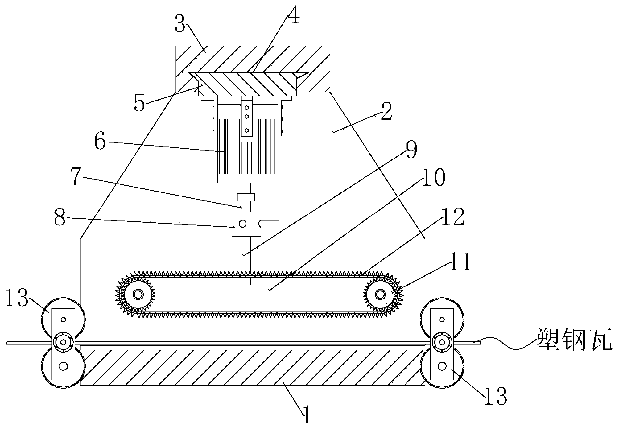
[0046] 1. Please refer to Figure 1-7 , is a schematic diagram of the overall structure of a plastic-steel tile manufacturing and processing machine, including a base 1. The base 1 is a square plate fixed horizontally on the ground. The top of the base 1 is fixed with a support plate 2 standing upright on the base 1. The support plate 2 has a trapezoidal structure. The top of the support plate 2 is fixed with a top support plate 3 arranged horizontally, and the bottom surface of the top support plate 3 is provided with a V-shaped structure chute 4, the chute 4 is perpendicular to the support plate 2, and the inside of the chute 4 A sliding seat 5 is embedded in a sliding fit, the bottom end of the sliding seat 5 is fixed with a hydraulic cylinder 6, the hydraulic cylinder 6 protrudes downwards from the piston rod 7, the bottom end of the piston rod 7 is fixed with an adjustment assembly 8, and the bottom of the adjustment assembly 8 A connecting rod 9 is installed at the end o...

Embodiment 2

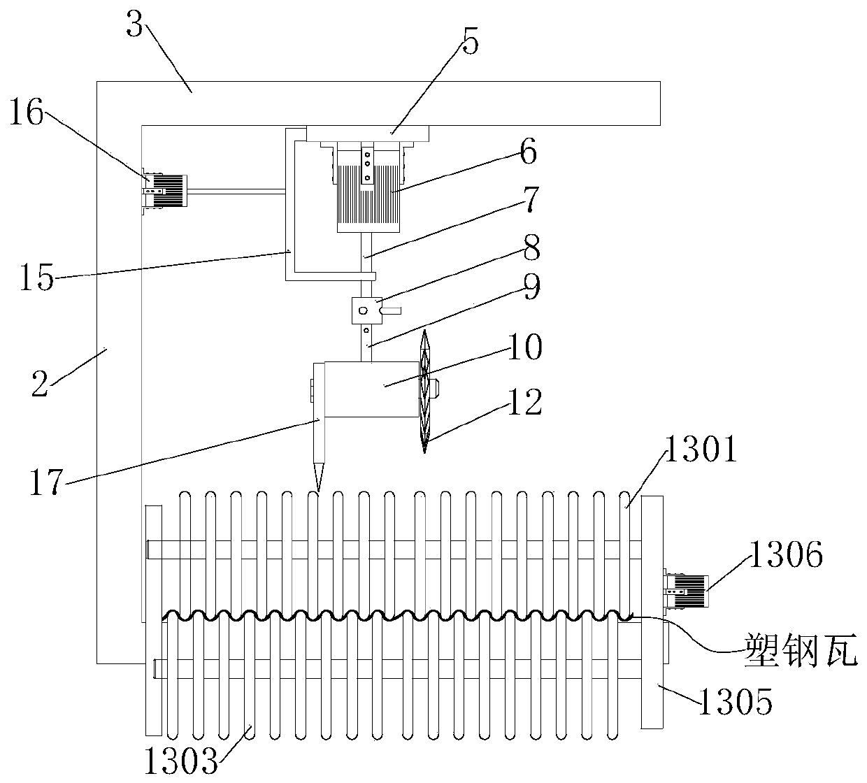
[0062] see Figure 1-8 , is a schematic diagram of the overall structure of a plastic-steel tile manufacturing and processing machine and processing method. This embodiment has the same content as the above-mentioned embodiment 1, and the similarities will not be described in this embodiment. The specific differences are:

[0063] A plastic-steel tile manufacturing and processing machine provided by the present invention includes the following methods of use:

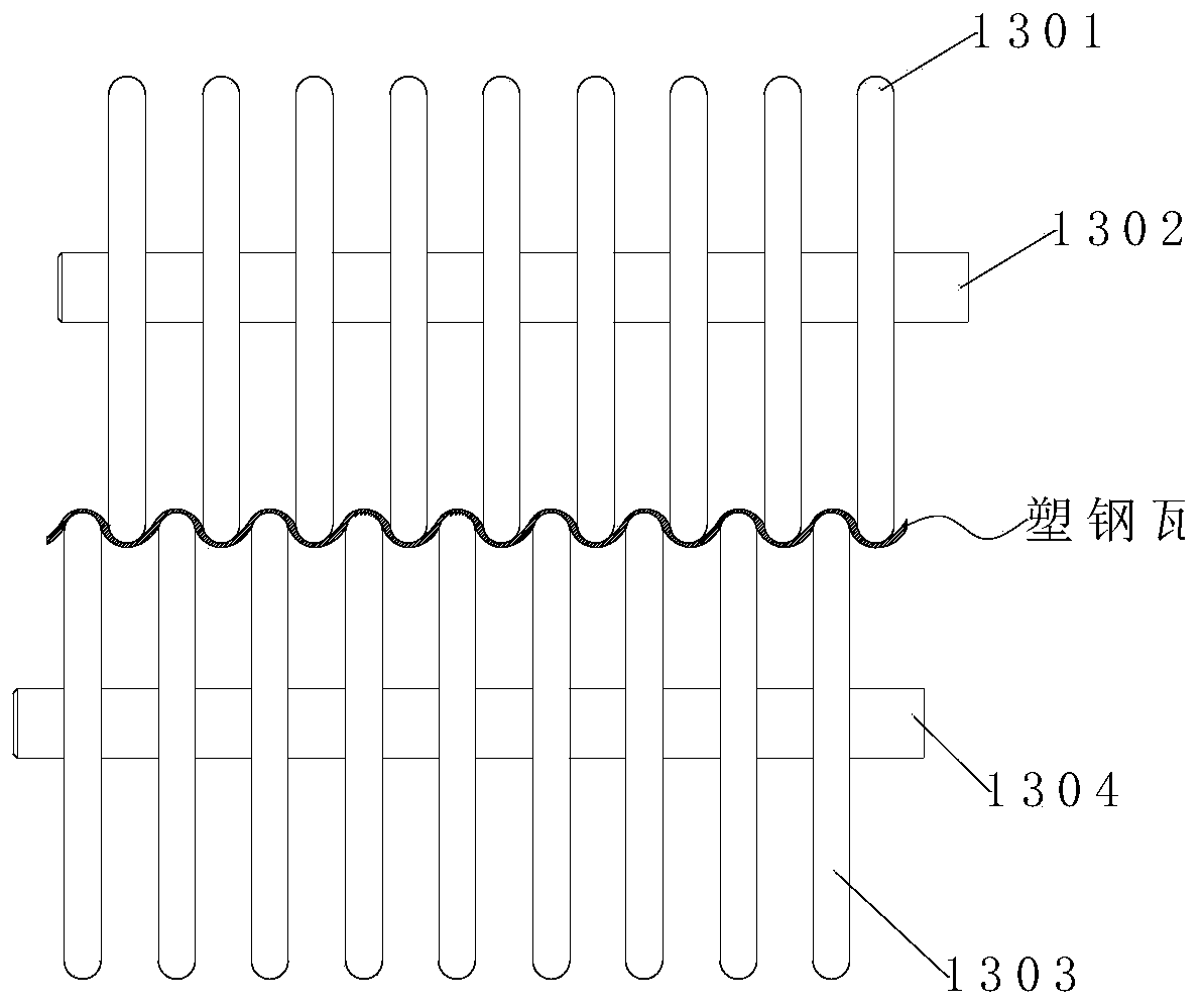
[0064] S1. Place the material, insert the plastic-steel tile from the transmission assembly 13, inserting refers to manually attaching the wave surface of the plastic-steel tile to the first transmission wheel 1301 and the second transmission wheel 1303 of the transmission assembly 13, through the transmission assembly 13 Move the plastic steel tile to the top of the base 1 at a constant speed;

[0065] S2. Longitudinal cutting of plastic-steel tiles. Slitting the plastic-steel tiles moved to the top of the base 1 in s...


PUM


Abstract

The invention discloses a machining machine and machining method for manufacturing plastic steel tiles and relates to the technical field of plastic steel tile machining and manufacturing. The machinecomprises a base. A square plate horizontally fixed to the ground is adopted as the base. A supporting plate erected to the base is fixed to the top end of the base. A top supporting plate arranged horizontally is fixed to the top end of the supporting plate. A sliding groove of a V-shaped structure is formed in the bottom end face of the top supporting plate. The sliding groove is perpendicularto the supporting plate. A sliding base is embedded into the sliding groove in a sliding fit manner. A hydraulic cylinder is fixed to the bottom end of the sliding base. An adjusting assembly is fixedto the bottom end of a piston rod. A connecting rod is installed at the bottom end of the adjusting assembly. According to the machine, the adjusting assembly is arranged on the connecting portion ofthe piston rod and the connecting rod, a rack can be rotated by 90 degrees through the adjusting assembly, under the circumstance that the plastic steel tiles cannot be moved, the plastic steel tilesare cut transversely and longitudinally, and accuracy of tailoring the plastic steel tiles is improved.

Description

technical field [0001] The invention relates to the technical field of plastic steel tile processing and manufacturing, in particular to a plastic steel tile manufacturing and processing machine and processing method. Background technique [0002] Plastic steel tiles, also known as PVC tiles, are named similar to the concept of plastic steel doors and windows. The main material is PVC, and other additives are added to improve product performance or processing performance, such as stabilizers, lubricants, strengtheners, etc. [0003] Plastic steel tiles have a series of characteristics such as anti-corrosion, lightning protection, anti-noise, high strength, and no pollution. They are widely used in portal steel structure workshops, chemical workshops, warehouses, coastal buildings and other fields. Almost all industrial industries as well as breeding and decoration industries can be divided into roof panels, non-demolition panels, wall panels and ceiling panels according to t...

Claims


Application Information

Patent Timeline
Patent Type & Authority Applications(China)
IPC IPC(8): B26D11/00B26D1/08B26D7/06B26D7/26B26D1/46
CPCB26D1/085B26D1/46B26D7/06B26D7/2628B26D11/00B26D2011/005
Inventor 郑文豪张伟健
Owner 荣泰建设集团有限公司
Why Eureka
Try Eureka