
A kind of 3D printing anti-grafting molding manufacturing method of mold for injection molding

A technology of 3D printing and manufacturing method, which is applied in the field of 3D printing reverse grafting molding of injection molds, which can solve problems such as complex structure, blockage, hidden dangers in use, etc., to achieve efficient and sufficient contact, ensure cooling effect, and ensure delivery speed effect

Active Publication Date: 2021-11-26
厦门雅信塑胶有限公司
View PDF9 Cites 0 Cited by
  • Summary
  • Abstract
  • Description
  • Claims
  • Application Information

AI Technical Summary

Problems solved by technology

If it is not cleaned, the powder will easily stick to the follow-up water channel when the subsequent coolant is introduced, burying hidden dangers for subsequent use
The existing cleaning methods are generally impacted by the compressed air of the atmospheric airflow, so as to realize the powder removal, but due to the complex structure of the conformal water channel and the existence of coils, the powder is easily crushed under the impact of the compressed air of the atmospheric airflow. The inner wall of the waterway has a mechanical bite, which directly forms a blockage. In severe cases, it may even cause the mold to be scrapped

Method used


Image

  • A kind of 3D printing anti-grafting molding manufacturing method of mold for injection molding
  • A kind of 3D printing anti-grafting molding manufacturing method of mold for injection molding
  • A kind of 3D printing anti-grafting molding manufacturing method of mold for injection molding

Examples


Embodiment 1

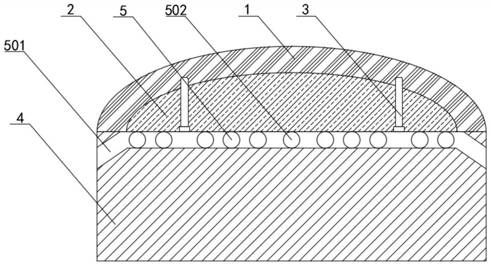
[0031] refer to figure 1 , a kind of 3D printing anti-grafting molding manufacturing method of mold for injection molding (the injection mold made by the present embodiment is the mouse upper cover production punch), and the specific molding steps are as follows:

[0032] 1) Forming of the mold end 1: the mold end 1 is formed by mold steel, and the end of the mold steel is processed into a convex arc shape according to the shape of the product through machining, and the bottom of the mold steel is processed into a The end of the mold has a consistent convex arc shape, and the end of the mold 1 is processed into a sheet shape suitable for the shape of the product;

[0033] 2) Processing of the cooling conduction pad 2: the cooling conduction pad 2 is made of beryllium copper material with excellent thermal conductivity, and the end of the cooling conduction pad 2 is processed into a convex arc shape consistent with the bottom of the mold steel, and The above-mentioned cooling ...

Embodiment 2

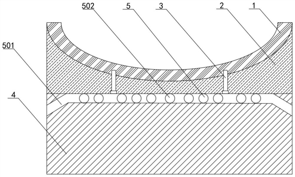
[0037] refer to figure 2 , a kind of 3D printing anti-grafting molding manufacturing method of mold for injection molding (the injection mold made in the present embodiment is the die for mouse upper cover production), and the specific molding steps are as follows:

[0038] 1) Forming of the mold end 1: the mold end 1 is formed by mold steel, and the end of the mold steel is processed into a concave arc shape according to the shape of the product through machining, and the bottom of the mold steel is processed into a The end of the mold has a consistent concave arc shape, and the end 1 of the mold is processed into a sheet shape suitable for the shape of the product;

[0039] 2) Processing of the cooling conduction pad 2: the cooling conduction pad 2 is made of beryllium copper material with excellent thermal conductivity, and the end of the cooling conduction pad 2 is processed into a concave arc shape consistent with the bottom of the mold steel, and The above-mentioned co...


PUM


Abstract

The invention relates to a 3D printing anti-grafting molding method of a mold for injection molding. The specific molding steps are as follows: 1) Mold end molding: the mold end is processed and formed by mold steel, and the end of the mold steel is processed into a corresponding shape according to the shape of the product. shape, and process the bottom of the mold steel into the same shape as the end of the mold steel, and process the end of the mold into a sheet shape that adapts to the shape of the product; Made of the best metal material or alloy material, the cooling conduction pad is embedded in the bottom of the mold steel, and the bottom of the cooling conduction pad is processed into a plane shape; 3) Mold core forming: the inside of the mold core is provided with The conformal waterway, the mold core and the conformal waterway are processed by 3D printing. The invention can shorten the time-consuming and cost of 3D printing molding, and can ensure the flatness of the injection end surface of the mold, and can effectively remove residual powder.

Description

technical field [0001] The invention relates to the technical field of mold manufacturing for injection molding, in particular to a method for making a mold for injection molding by 3D printing reverse grafting. Background technique [0002] Injection mold is a tool for producing plastic products, and it is also a tool for giving plastic products complete structure and precise dimensions. Since the injection mold needs to have a cooling effect during injection molding production, the existing injection mold itself is generally provided with corresponding cooling water channels distributed through machining. Since the shapes of many injection molded products are irregular curved surfaces, for example, the top cover of the mouse is in the shape of an upward convex arc, which requires the contact surface between the injection mold and the injection molding material to have an irregular shape. Most of the cooling water channels formed by machining are straight lines, which are ...

Claims


Application Information

Patent Timeline
Patent Type & Authority Patents(China)
IPC IPC(8): B29C33/38B29C45/26B23P15/24
CPCB23P15/24B29C33/3842B29C45/2602
Inventor 林荣川
Owner 厦门雅信塑胶有限公司
Learn More