Sampling device and sampling method for low concentration total particles in smoke of thermal power plant
A sampling device and particulate matter technology, applied in the field of fixed source flue gas testing, can solve the problems of increasing escapable particulate matter emissions and rapidly increasing proportion, and achieve the effects of reducing errors, suppressing adsorption, and avoiding excessive escape.
- Summary
- Abstract
- Description
- Claims
- Application Information
AI Technical Summary
Problems solved by technology
Method used
Image
Examples
Embodiment 1
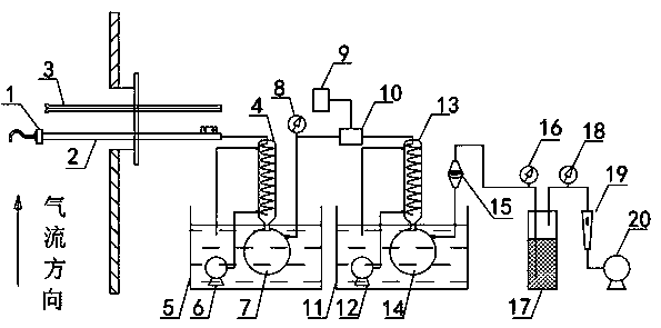
[0049] Such as figure 1 As shown, the low-concentration total particulate matter sampling device in the flue gas of a thermal power plant of the present invention includes a sampling device, a condensation device, a secondary filter membrane 15 (PPM filter membrane), a drier 17, a metering device and Sampling pump 20. Pitot tube 3 is also provided in the device.
[0050] The sampling device includes an integrated sampling head 1 and a heating sampling gun 2. The integrated sampling head 1 is composed of a sampling nozzle and a primary filter membrane (FPM filter membrane), the heating sampling gun is lined with a heating sleeve, and the heating sampling gun 2 tubes The heating temperature of the outer lining heating sleeve is controlled at 120°C ± 5°C.
[0051] The condensing device is divided into two stages connected in series. The two-stage condensing devices are equipped with a spiral condensing tube and an impact bottle. The spiral condensing tube is vertically installe...
Embodiment 2
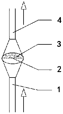
[0059] Such as figure 2 As shown, in this example, optionally, the secondary filter membrane 15 adopts an inverted structure; The inverted filter membrane material of the secondary filter membrane 15 is a PTFE membrane; for standard particles with a diameter of 0.3 μm, the trapping efficiency of the secondary filter should be greater than 99.5%. The primary filter membrane adopts quartz membrane or PTFE membrane; for standard particles with a diameter of 0.3 μm, the collection efficiency of the primary filter should be greater than 99.5%.
Embodiment 3
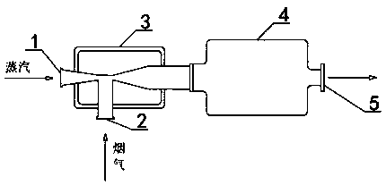
[0061] Such as image 3 As shown, optional in this example, the enhanced phase change system 10 is designed as shown in the figure. The enhanced phase change system includes a jet mixer 3 and a phase change chamber 4 connected front and back. The jet mixer 3 is provided with two inlets, and the two inlets are respectively It is used to connect steam and connect to the pre-stage condensing device. The jet mixer 3 communicates with the phase change chamber 4, and the phase change chamber 4 is provided with a mixed gas outlet for connecting to the post-stage condensing device.
[0062] The invention mixes the steam and the flue gas by means of jet flow, and the mixed flue gas enters the enhanced phase change system. The length, width and height of the phase change chamber are 600mm*50mm*50mm to ensure that the flue gas stays in the enhanced phase change system for no less than 10 seconds.
PUM
| Property | Measurement | Unit |
|---|---|---|
| diameter | aaaaa | aaaaa |
Abstract
Description
Claims
Application Information
 - R&D
- Intellectual Property
- Life Sciences
- Materials
- Tech Scout
- Unparalleled Data Quality
- Higher Quality Content
- 60% Fewer Hallucinations
Browse by: Latest US Patents, China's latest patents, Technical Efficacy Thesaurus, Application Domain, Technology Topic, Popular Technical Reports.
© 2025 PatSnap. All rights reserved.Legal|Privacy policy|Modern Slavery Act Transparency Statement|Sitemap|About US| Contact US: help@patsnap.com


