Projection screen

A projection screen and projection technology, used in optics, instruments, projection devices, etc., can solve the problems of complex production methods, high costs, and difficult processes, reducing process difficulties and screen costs, saving coating costs, and increasing transmission. rate effect

Active Publication Date: 2020-02-04
APPOTRONICS CORP LTD
View PDF26 Cites 2 Cited by
  • Summary
  • Abstract
  • Description
  • Claims
  • Application Information

AI Technical Summary

Problems solved by technology

However, when the projection system is installed in a bright living room, where there is a lot of stray light, there are usually some problems with the image display on the projection screen. The screen will reflect the ambient light, which will cause interference to the signal light, and it is difficult to obtain a good contrast
For screens with a prism structure, in order to solve the above problems, it is necessary to coat the side of the raised prism structure facing the ambient light on the roof with a light-absorbing layer, and the side facing the projection light to be coated with a reflective layer. This process is difficult and costly. Absorb part of the ambient light from above, and cannot absorb ambient light from other directions
[0003] For example, the technical solutions disclosed in patent documents KR1256594B1 and JP4047172 are to selectively coat a light-absorbing layer on a specific area of ​​the Fresnel structure in the reflective screen. Absorb ambient light in the same direction as projected light, and the production method is complicated and costly

Method used


Image

  • Projection screen
  • Projection screen
  • Projection screen

Examples


Embodiment 1

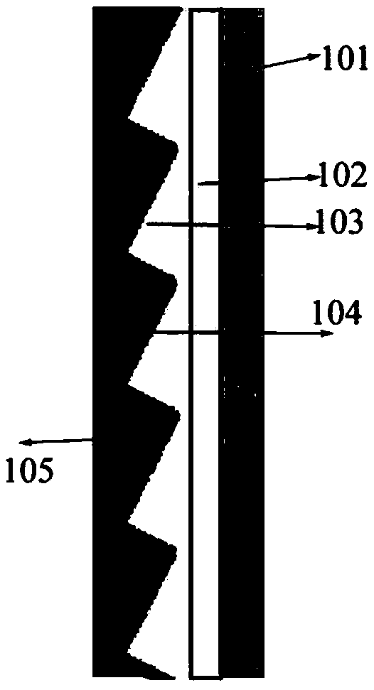
[0033] figure 2 It is a schematic structural diagram of a projection screen according to Embodiment 1 of the present invention. Such as figure 2 As shown, in this embodiment, the projection screen includes a diffusion layer 101 , a substrate layer 102 , a Fresnel structure layer 103 , a reflection layer 104 and a light absorption layer 105 arranged in sequence along the incident direction of the projection light.

[0034] Specifically, the diffusion layer 101 is a surface diffusion layer, one side of the surface diffusion layer has a microstructure (surface diffusion structure), and the surface diffusion layer has no microstructure and the substrate layer 102 (transparent PET) with a transparent For adhesive bonding, apply photosensitive adhesive (such as UV curable adhesive) on the side of the substrate layer 102 away from the diffusion layer 101, the thickness of the photosensitive adhesive is 10 μm-100 μm, preferably 20 μm-50 μm. The Fresnel structure is transferred to ...

Embodiment 2

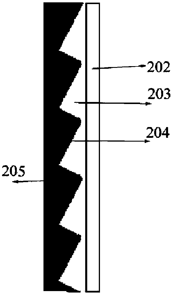
[0039] image 3 It is a schematic structural diagram of the projection screen in Embodiment 2 of the present invention. Such as image 3 As shown, the difference between this embodiment and the first embodiment is that the projection screen does not have a separate diffusion layer, but a surface diffusion structure is processed on the outer surface of the substrate layer 202, and the surface diffusion structure is used to realize the diffusion layer. function.

[0040] Specifically, in this embodiment, the projection screen includes a substrate layer 202 , a Fresnel structure layer 203 , a reflective layer 204 and a light-absorbing layer 205 sequentially arranged along the incident direction of the projection light.

[0041] When producing the above-mentioned projection screen, first set the surface diffusion structure on one side of the substrate layer 202, and then coat the photosensitive adhesive on the side of the substrate layer 202 without the surface diffusion structu...

Embodiment 3

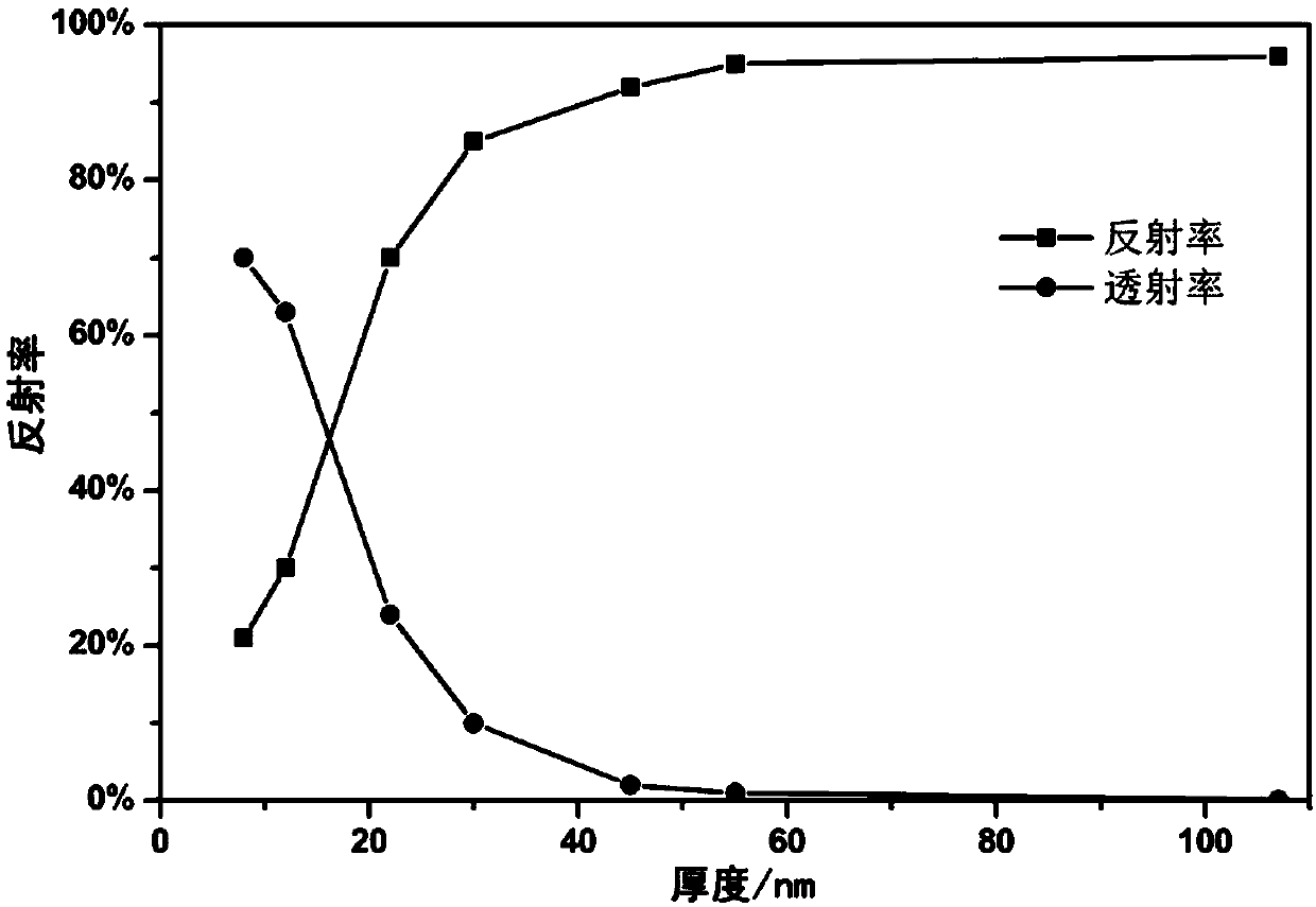
[0044] Figure 4 It is a schematic structural diagram of a projection screen according to Embodiment 3 of the present invention. Such as Figure 4As shown, in this embodiment, the projection screen includes a reflection layer 304 , a Fresnel structure layer 303 , and a substrate layer 302 sequentially arranged along the incident direction of the projection light. The reflective layer 304 has a thickness of 12nm and a reflectivity of 25%.

[0045] In this embodiment, no light-absorbing layer is provided separately, and the base material layer 302 is black in order to absorb ambient light passing through the reflective layer.

[0046] Similar to the second embodiment, this embodiment does not provide a separate diffusion layer, but a surface diffusion structure is provided on the outer surface of the reflective layer 304, and the function of the diffusion layer is realized by using the surface diffusion structure.

[0047] It should be noted that the surface diffusion structu...


PUM

PropertyMeasurementUnit
thicknessaaaaaaaaaa
thicknessaaaaaaaaaa
thicknessaaaaaaaaaa

Abstract

The invention relates to a projection screen. The projection screen comprises a reflecting layer, a Fresnel structure layer and a substrate layer which are arranged in sequence; and the thickness of the reflecting layer is 7-25 nm. According to the projection screen in the invention, the thickness of the reflecting layer in the projection screen is reduced, therefore, the transmittance of the reflecting layer is increased, a light absorption layer does not need to be selectively coated on the Fresnel structure layer additionally, ambient light in all directions can be absorbed, and the high contrast effect is achieved; and furthermore, the thickness of the reflecting layer is reduced, the film coating cost is reduced, and the process difficulty and the screen cost are reduced.

Description

technical field [0001] The invention relates to a projection screen, in particular to a projection screen with high contrast. Background technique [0002] In recent years, a projection system has been developed to realize projection on a large screen exceeding 100 inches when the distance between the projector and the screen is 50cm. The projection system can overcome the limitation of installation space. However, when the projection system is installed in a bright living room, where there is a lot of stray light, there are usually some problems with the image display on the projection screen. The screen will reflect the ambient light, which will cause interference to the signal light, and it is difficult to obtain a good contrast. For screens with a prism structure, in order to solve the above problems, it is necessary to coat the side of the raised prism structure facing the ambient light on the roof with a light-absorbing layer, and the side facing the projection light...

Claims


Application Information

Patent Timeline
Patent Type & Authority Applications(China)
IPC IPC(8): G03B21/602G03B21/60
CPCG03B21/602G03B21/60
Inventor 张红秀王霖王杰李屹
Owner APPOTRONICS CORP LTD
Why Eureka
Try Eureka