
Pebble bed water-rich deep foundation pit protective structure adjacent to existing high-speed rail

A technology for deep foundation pits and pebble layers, which is used in infrastructure engineering, excavation, construction, etc., can solve problems such as poor stability of horizontal support rods, stratum landslides, and collapse and rupture of water-stop walls, and achieve the effect of avoiding deformation.

Pending Publication Date: 2020-02-07
向怀轶
View PDF5 Cites 0 Cited by
  • Summary
  • Abstract
  • Description
  • Claims
  • Application Information

AI Technical Summary

Problems solved by technology

[0004] 1. When pouring supports and water-stop walls on the inner wall of the deep foundation pit near the railway line, the traditional protective structure is to first scrape the inner wall of the deep foundation pit and then pour the water-stop wall directly on the inner wall. In the process of scraping the inner wall of the deep foundation pit, it is easy to cause landslides in the ground, which makes it easy to deform the track during the construction process, and the pouring is difficult
[0005] 2. The design of the whole block of water-stop wall reduces the yield strength of the water-stop wall to the support of the ground, and it is easy to accumulate the pressure generated by the water-stop wall on the ground, making the water-stop wall prone to collapse and rupture
[0006] 3. The support rods of the traditional protective structure are fixed horizontally on the upper and lower sides of the deep foundation pit. When the ground deformation occurs on one side of the deep foundation pit, the stability of the horizontal support rods is poor, and it is easy to follow the deformation of the ground. Tilting, so that the supporting capacity of the support bar for the formation on both sides is reduced

Method used


Image

  • Pebble bed water-rich deep foundation pit protective structure adjacent to existing high-speed rail
  • Pebble bed water-rich deep foundation pit protective structure adjacent to existing high-speed rail
  • Pebble bed water-rich deep foundation pit protective structure adjacent to existing high-speed rail

Examples


Embodiment Construction

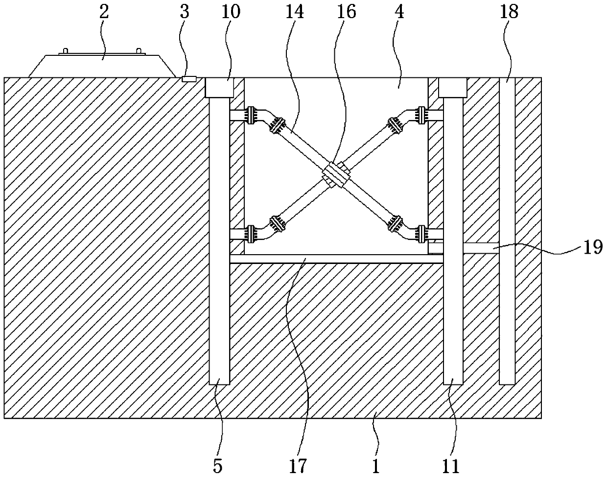
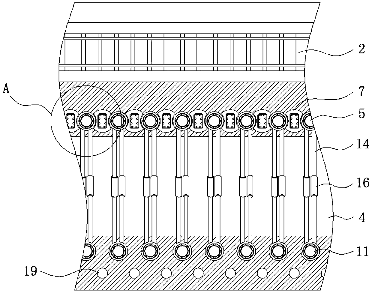
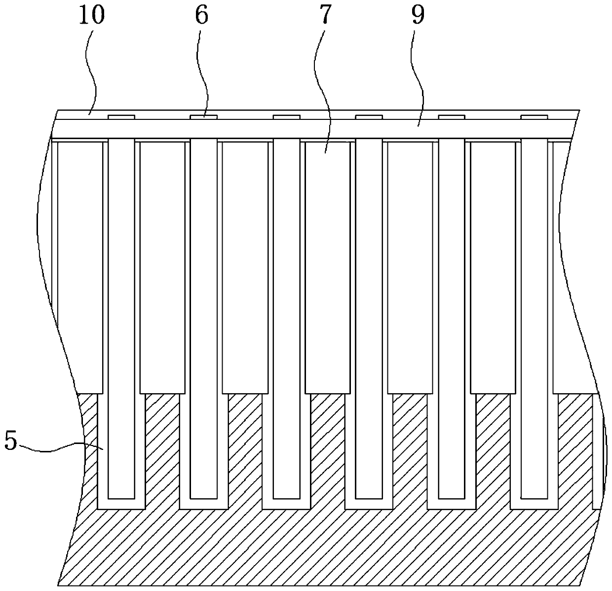
[0029] The following will clearly and completely describe the technical solutions in the embodiments of the present invention with reference to the accompanying drawings in the embodiments of the present invention. Obviously, the described embodiments are only some, not all, embodiments of the present invention. Based on the embodiments of the present invention, all other embodiments obtained by persons of ordinary skill in the art without making creative efforts belong to the protection scope of the present invention.

[0030] The embodiment of the water-rich deep foundation pit protection structure adjacent to the existing high-speed rail pebble layer is as follows:

[0031] see Figure 1-6 , a protective structure for rich water deep foundation pit adjacent to the existing high-speed rail pebble layer, including 1. ground; 2. high-speed rail line; 3. deformation observation point; 4. deep foundation pit; Reinforcement cage; 7. Occlusion water stop pile; 8. Rectangular rein...


PUM


Abstract

The invention provides a pebble bed water-rich deep foundation pit protective structure adjacent to an existing high-speed rail, and relates to the technical field of deep foundation pit protection. The pebble bed water-rich deep foundation pit protective structure adjacent to the existing high-speed rail comprises the ground, the top end of the ground is paved with a high-speed rail line, a deformation observation point is fixedly installed on the right side of the high speed rail line, the surface of the ground is provided with a deep foundation pit, the left side of the deep foundation pitin the ground is provided with drilled fender posts through pouring, and round reinforcement cages are placed in the drilled fender posts. According to the pebble bed water-rich deep foundation pit protective structure adjacent to the existing high-speed rail, processing of the inner wall of the deep foundation pit is avoided, and convenience and rapidness are achieved better; meanwhile, influenceon internal stress of the ground is small, deformation of the rail in the construction process is avoided, the yield strength, for stratum supporting, of the drilled fender posts and interlocking water stopping posts is improved, the supporting effect on the stratum is improved, and the stability of supporting rods is improved.

Description

technical field [0001] The invention relates to the technical field of deep foundation pit protection, in particular to a water-rich deep foundation pit protection structure adjacent to an existing high-speed iron pebble layer. Background technique [0002] With the development of urban construction, there are more and more deep foundation pits adjacent to the existing high-speed railway in operation. Since the high-speed ballastless track is extremely sensitive to deformation, it is almost a "zero settlement" requirement for the ballastless track high-speed railway in operation. When the stratum is In sand and pebble layers with strong water permeability, the groundwater level is often high. The excavation and precipitation of conventional foundation pits will have varying degrees of impact on the adjacent existing high-speed ballastless track railway, and even endanger the safety of high-speed railway operation. Therefore, it is necessary to build a protective structure in...

Claims


Application Information

Patent Timeline
IPC IPC(8): E02D17/04
CPCE02D17/04
Inventor 蔡铭涂阳阳王湘惠吴官宝麻时光赵贵龙
Owner 向怀轶
Learn More