
Photovoltaic bionic photoelectrocatalysis integrated air treatment system

An air treatment system, photoelectric catalysis technology, applied in air conditioning systems, space heating and ventilation, heating methods, etc., can solve the problems of complex photocatalytic device equipment, single photocatalytic unit structure, high operating costs, and achieve the goal of providing light energy. utilization, improving system energy efficiency, and reducing operating costs

Active Publication Date: 2020-02-07
ANHUI SCI & TECH UNIV
View PDF8 Cites 1 Cited by
  • Summary
  • Abstract
  • Description
  • Claims
  • Application Information

AI Technical Summary

Problems solved by technology

[0010] What the present invention is to overcome are the problems of complex photocatalytic device equipment, single structure of photocatalytic unit, low unit efficiency and high operating cost in the prior art, and the purpose is to provide a photovoltaic bionic photocatalytic integrated air treatment system

Method used


Image

  • Photovoltaic bionic photoelectrocatalysis integrated air treatment system
  • Photovoltaic bionic photoelectrocatalysis integrated air treatment system
  • Photovoltaic bionic photoelectrocatalysis integrated air treatment system

Examples


Embodiment 1

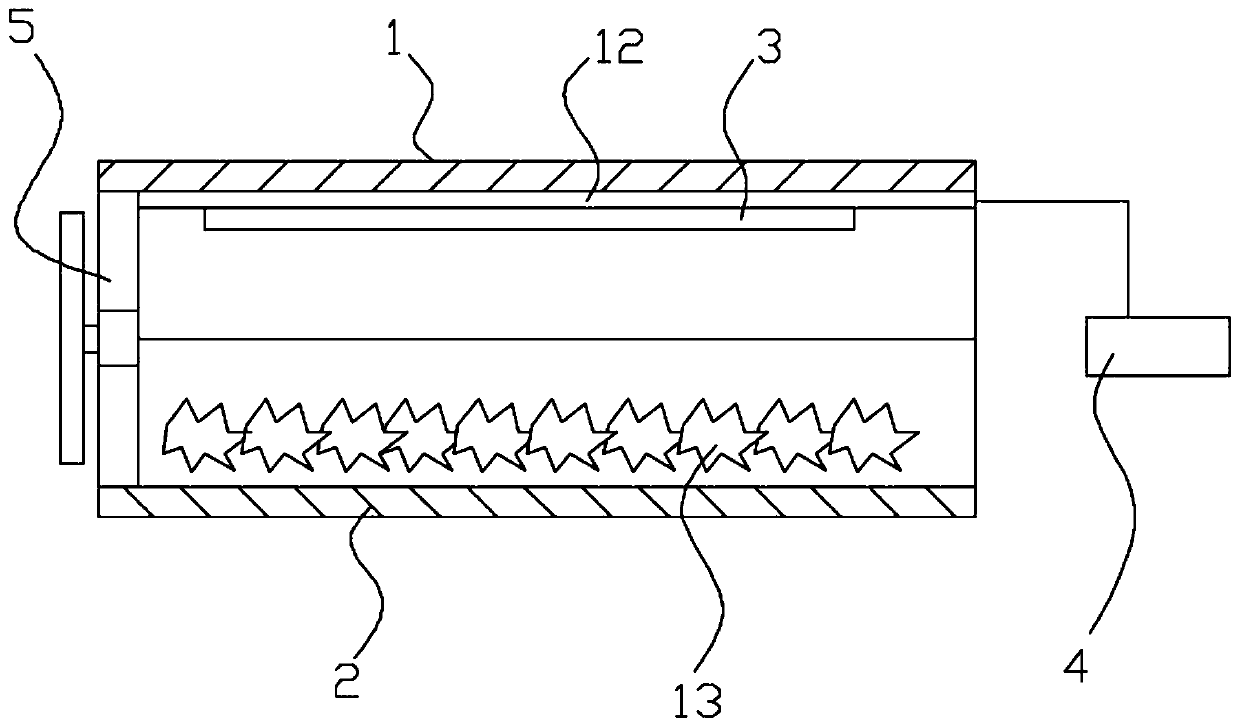
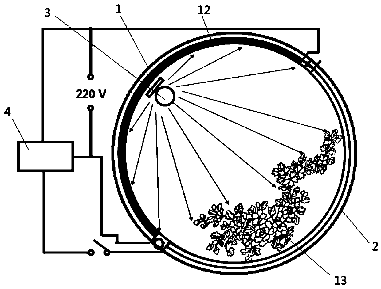
[0036] Such as figure 1 , figure 2 , image 3 Shown; A photovoltaic biomimetic photoelectric catalysis integrated air treatment system, comprising:

[0037] Photovoltaic power generation unit housing 1, photocatalytic purification unit housing 2, ultraviolet light source 3, fan 5 and battery system 4;

[0038] Both the housing 1 of the photovoltaic power generation unit and the housing 2 of the photoelectric catalytic purification unit are in the shape of a semicircular tube, and the sides of the two are hinged to form a cylindrical structure. A fan 5 is installed at one end of the structure, and the fan 5 is connected to the battery system 4 A solar panel 12 is installed inside the housing 1 of the photovoltaic power generation unit, the solar panel 12 is connected to the battery system 4, the ultraviolet light source 3 is installed on the inside of the housing 1 of the photovoltaic power generation unit, the ultraviolet light source 3 is connected to the battery system 4,...

Embodiment 2

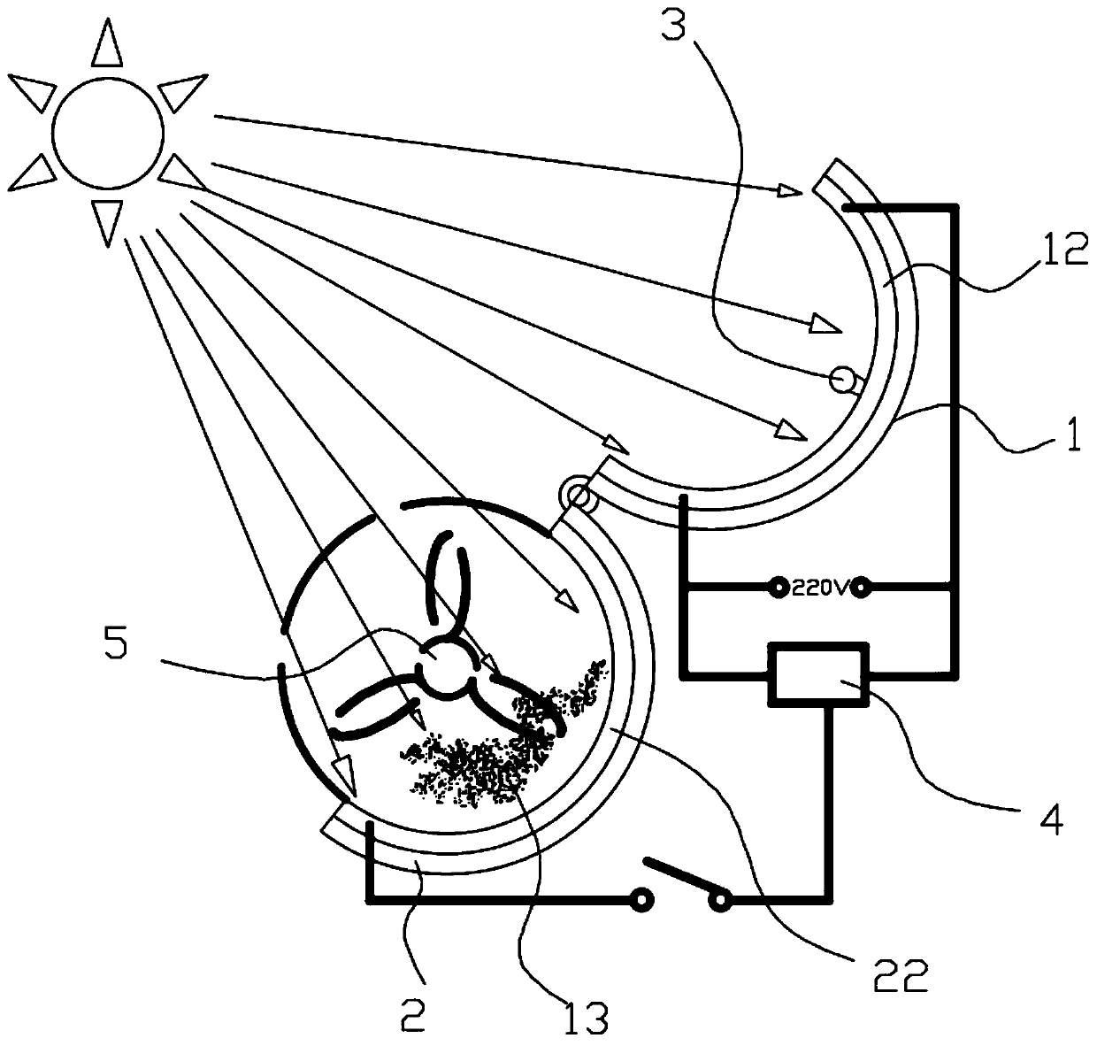
[0043] Such as figure 2 , image 3 , Figure 4 Shown; A photovoltaic biomimetic photoelectric catalysis integrated air treatment system, comprising:

[0044] Photovoltaic power generation unit housing 1, photocatalytic purification unit housing 2, ultraviolet light source 3, fan 5 and battery system 4;

[0045] Both the housing 1 of the photovoltaic power generation unit and the housing 2 of the photoelectric catalytic purification unit are in the shape of a semicircular tube, and the sides of the two are hinged to form a cylindrical structure. A fan 5 is installed at one end of the structure, and the fan 5 is connected to the battery system 4 A solar panel 12 is installed inside the housing 1 of the photovoltaic power generation unit, the solar panel 12 is connected to the battery system 4, the ultraviolet light source 3 is installed on the inside of the housing 1 of the photovoltaic power generation unit, the ultraviolet light source 3 is connected to the battery system 4...


PUM


Abstract

The invention discloses a photovoltaic bionic photoelectrocatalysis integrated air treatment system, and relates to the field of air pollution control equipment. The system comprises a photovoltaic power generation shell, a photoelectrocatalysis purification unit shell, an ultraviolet source, a fan and a storage battery system. The photovoltaic power generation shell and the photoelectrocatalysispurification unit shell are both of semi-circular tubular structures, the side edges of one sides of the photovoltaic power generation shell and the photoelectrocatalysis purification unit shell are hinged to form a cylindrical structure, one end of the structure is provided with the fan, the fan is connected with the storage battery system, the inner side of the photovoltaic power generation shell is provided with a solar cell panel, the solar cell panel is connected with the storage battery system, the ultraviolet source is arranged on the inner side of the photovoltaic power generation shell, the ultraviolet source is connected with the storage battery system, and a bionic photocatalysis assembly is arranged on the inner side of the photoelectrocatalysis purification unit shell and photosensitive resin mixed with a photocatalyst. A photocatalysis device is simplified, the running cost is reduced, and the solar use rate is improved.

Description

technical field [0001] The invention relates to the field of air pollution control equipment, in particular to a photovoltaic bionic photoelectric catalysis integrated air treatment system. Background technique [0002] With the acceleration of industrialization and urbanization, air pollution has brought serious harm to the ecological environment and human health. Especially the Volatile Organic Compounds (VOCs) released by industrial production can lead to harmful substances such as photochemical smog and PM2. The main pollutants emitted by exhaust gas in various chemical production processes. Most of the high-concentration VOCs-containing waste gas produced by industrial production adopts recovery technology to reduce emissions, and the degradation of medium- and low-concentration VOCs-containing waste gas is a better treatment method. Volatile organic compounds (TVOC) emitted by various indoor building decoration materials with a boiling point of 50°C-250°C can induce ...

Claims


Application Information

Patent Timeline
Patent Type & Authority Applications(China)
IPC IPC(8): F24F3/16F24F5/00
CPCF24F5/0046F24F5/0096F24F2005/0067F24F2221/18F24F8/22F24F8/192
Inventor 郭雨陈君华金晶上官岳峰张炎李晨瑶汪楷丽袁家凤
Owner ANHUI SCI & TECH UNIV
Learn More