Unlock instant, AI-driven research and patent intelligence for your innovation.

Microfluidic Analysis Equipment

A device, analyte technology, applied in the direction of fluid controller, biochemical device and method, determination/inspection of microorganisms, etc., can solve problems such as the limitation of the degree to which the speed at which the droplet can move can be changed

Active Publication Date: 2022-07-08
LIGHTCAST DISCOVERY LTD
View PDF15 Cites 0 Cited by
  • Summary
  • Abstract
  • Description
  • Claims
  • Application Information

AI Technical Summary

Problems solved by technology

Additionally, there are limits to how fast a droplet can move and how much the actual droplet path can change

Method used


Image

  • Microfluidic Analysis Equipment
  • Microfluidic Analysis Equipment
  • Microfluidic Analysis Equipment

Examples


Embodiment Construction

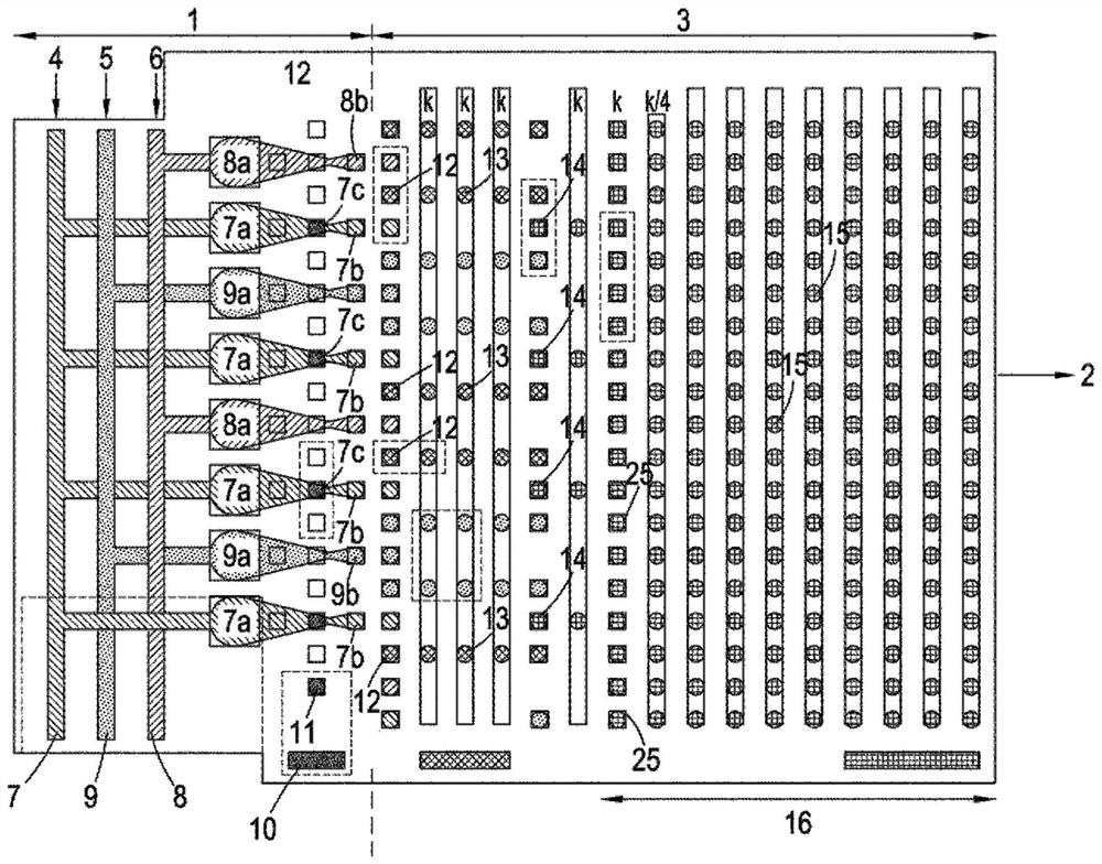
[0082] Apparatus suitable for sequencing polynucleotide DNA analytes according to the present invention will now be illustrated by the following figures and description.

[0083] figure 1 A top view of a microfluidic substrate is shown comprising a droplet preparation area 1 and a droplet manipulation area 3 integrated into a single unit made of transparent plastic. in the substrate. 1 includes regions 7, 8, and 9 containing fluids attached to inlets 4, 5, and 6, which introduce pyrophosphate hydrolysis streams, inorganic pyrophosphatase streams, and various Detect the flow of chemicals and enzymes required to identify nucleoside triphosphates according to one of our earlier patent applications. These streams are then delivered to orifices 7a, 8a, and 9a, respectively, from which various droplets 7b, 8b, and 9b are produced (eg, using a drop-dispensing head or by cutting out of larger intermediate droplets). 10 is a reservoir containing paramagnetic polymer composite microb...


PUM


Abstract

An apparatus for studying nucleic acid analytes, characterized by comprising: a first area, the first area including an attachment site to which the analyte is attached; a first path, the first path for causing a first fluid medium to flow through the attachment site so that the nucleic acid is progressively pyrophosphorylated into its constituent nucleoside triphosphates; a second pathway for transferring from the attachment site surrounding removal of said nucleoside triphosphates, and means for generating a second medium in a second pathway, said second medium comprising aqueous droplets in a water-immiscible carrier; a droplet manipulation zone, which Using optically mediated electrowetting to manipulate droplets, the droplet manipulation zone includes: a first composite wall including a first transparent substrate; a first transparent conductor layer on the substrate, the thickness of the first transparent conductor layer in the range of 70 to 250 nm; on the conductor layer there is a photoactive layer activated by electromagnetic radiation having a wavelength in the range of 400-1000 nm, the photoactive layer thickness is in the range of 300-1000 nm, and a first dielectric layer on the conductor layer, No. a dielectric layer having a thickness in the range of 120 to 160 nm; a second composite wall including a second substrate; a second conductor layer on the substrate, the second conductor layer having a thickness in the range of 70 to 250 nm, and optionally, a second dielectric layer on the conductor layer, the thickness of the second dielectric layer is in the range of 120 to 160 nm; wherein the exposed surfaces of the first dielectric layer and the second dielectric layer are spaced apart by less than 10 μm to A microfluidic space adapted to contain the droplets is defined. A / C source for providing a voltage across the first composite wall and the second composite wall, the first composite wall and the second composite wall connecting the first conductor layer and the second conductor layer; the first source of electromagnetic radiation, Its energy is higher than the bandgap of the photoexcitable layer, which is adapted to act on the photoactive layer to induce corresponding temporary first electrowetting sites on the surface of the first dielectric layer; for manipulating electromagnetic radiation on the photoactive layer a point of action on the device to change the arrangement of temporal electrowetting positions to form at least one first electrowetting path along which droplet movement can be caused; a detection zone located downstream of the droplet manipulation zone or Integrated with the droplet manipulation zone, and a fluorescence or Raman scattering detection system comprising a second source of electromagnetic radiation and a detector, the second source of electromagnetic radiation adapted to act on droplets in the detection zone, the detection The detector is used to detect the fluorescence or Raman scattering emitted therefrom.

Description

technical field [0001] The present invention relates to a device for the study of nucleic acid molecules; in particular, a device for sequencing DNA or RNA of natural or synthetic origin. Background technique [0002] In our previous applications WO 2014 / 053853, WO 2014 / 053854, WO2014 / 167323, WO2014 / 167324 and WO2014 / 111723, we have described a novel sequencing method involving stepwise digestion of polynucleotide analytes ( polynucleotide analyte) to produce an ordered stream of single nucleotides, preferably a stream of single nucleoside triphosphates, each of which can be captured one-by-one into a corresponding stream of droplets in droplets. Thereafter, each droplet can be chemically and / or enzymatically treated to reveal the specific single nucleotide it originally contained. In one embodiment, these chemical and / or enzymatic treatments include a method involving the use of one or more two-component oligonucleotide probe types, each type being adapted It is one of t...

Claims


Application Information

Patent Timeline
Patent Type & Authority Patents(China)
IPC IPC(8): B01L3/00C12Q1/6869
CPCB01L3/5027C12Q1/6869B01L2200/10B01L3/502792B01L2200/0673B01L2300/0864B01L2300/0887B01L2300/089B01L2300/161B01L2300/165B01L2300/168B01L2400/0427
Inventor 托马斯·亨利·艾萨克佩德罗·昆哈艾厄因·谢里丹大卫·拉乌丽贝卡·帕尔莫道格拉斯·J·凯利加雷斯·鲍德
Owner LIGHTCAST DISCOVERY LTD
Features
  • R&D
  • Intellectual Property
  • Life Sciences
  • Materials
  • Tech Scout
  • Unparalleled Data Quality
  • Higher Quality Content
  • 60% Fewer Hallucinations
Learn More