Garbage biochemical treatment machine
A biochemical processor and garbage technology, applied in grain processing, chemical instruments and methods, and solid waste removal, etc., can solve the problems of untimely discharge of water vapor, long biochemical treatment time, and smelly water vapor.
- Summary
- Abstract
- Description
- Claims
- Application Information
AI Technical Summary
Problems solved by technology
Method used
Image

Examples
Embodiment 1
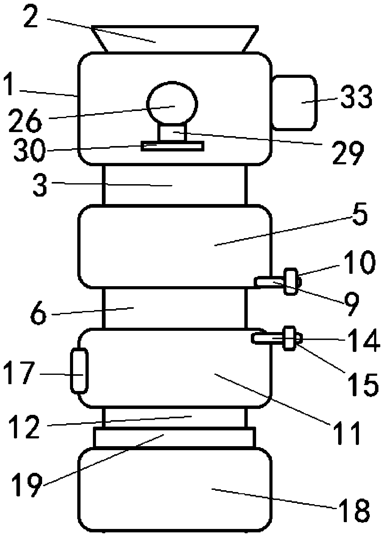
[0016] according to figure 1 , a garbage biochemical treatment machine, which mainly includes: a crushing box 1, the crushing box 1 is set as a cavity, and the top is provided with a feed port 2, and the bottom is provided with a first discharge channel 3, and the first discharge channel 3 is provided. A first high-pressure sealing valve plate is provided in the material channel 3; a multi-stage crushing device is arranged inside the crushing box 1; a hyperbaric chamber 5 is longitudinally arranged in the crushing box 1 below the cylindrical structure, the top of the hyperbaric chamber 5 communicates with the first discharge channel 3, the bottom of the hyperbaric chamber 5 is provided with a second discharge channel 6, and the second discharge channel 6 is provided with There is a second high-pressure sealing valve plate; the inner wall of the hyperbaric chamber 5 is fixedly provided with an electric heating element, and the bottom of the inner wall of the hyperbaric chamber ...
Embodiment 2
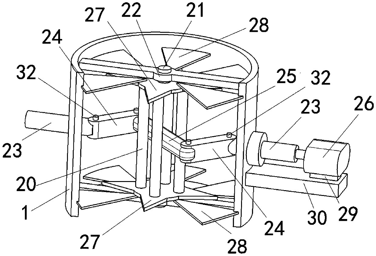
[0019] according to figure 2 , the multi-stage crushing device includes a reciprocating rotating frame 20 longitudinally arranged inside the crushing box 1, the reciprocating rotating frame 20 is a rolling cage structure, and the upper and lower ends are respectively provided with outwardly extending shaft heads 21, so The shaft head 21 is connected to the inner side wall of the crushing box 1 through a bearing frame 22; it also includes shaft holes that coaxially pass through the inner walls of the opposite sides of the crushing box 1, and the axis of each shaft hole is connected with the reciprocating rotating frame. The axis of rotation of 20 intersects vertically; each said shaft hole is provided with an optical axis 23 one by one, and one end close to each said optical axis 23 is respectively connected with a swing arm 24, and each said swing arm 24 is arranged parallel to each other; each said One end of the swing arm 24 away from the optical axis 23 is connected to eac...
Embodiment 3
[0022] Both ends of each swing arm 24 are respectively hinged to the corresponding optical axis 23 and the connecting rod 25; the drive motor 26 is connected to the outer side wall of the crushing box 1 through an axial movement mechanism, and the shaft The moving mechanism includes a slide rail 30 arranged parallel to the optical axis 23, and the slide rail 30 is equipped with a slide block 29, and the drive motor 26 is fixedly connected with the slide block 29; it also includes an electric cylinder, and the electric drive The cylinder is arranged parallel to the slide rail 30 , and the fixed end of the electric cylinder is connected to the slide rail 30 , and the telescopic end of the electric cylinder is fixedly connected to the slider 29 .
[0023] In the above arrangement, the drive motor 26 reciprocates along the direction of the optical axis 23 through the cooperation of the slider 29 and the slide rail 30. Especially during the rotation, when the drive motor 26 moves to...
PUM
 Abstract
Description
Claims
Application Information
 - R&D
- Intellectual Property
- Life Sciences
- Materials
- Tech Scout
- Unparalleled Data Quality
- Higher Quality Content
- 60% Fewer Hallucinations
Browse by: Latest US Patents, China's latest patents, Technical Efficacy Thesaurus, Application Domain, Technology Topic, Popular Technical Reports.
© 2025 PatSnap. All rights reserved.Legal|Privacy policy|Modern Slavery Act Transparency Statement|Sitemap|About US| Contact US: help@patsnap.com